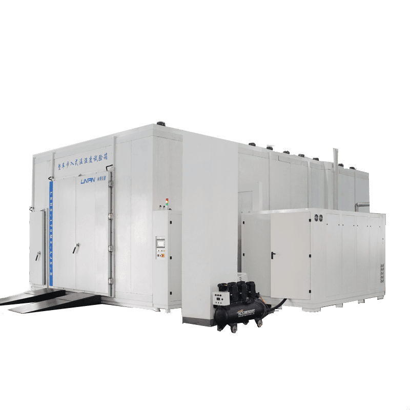
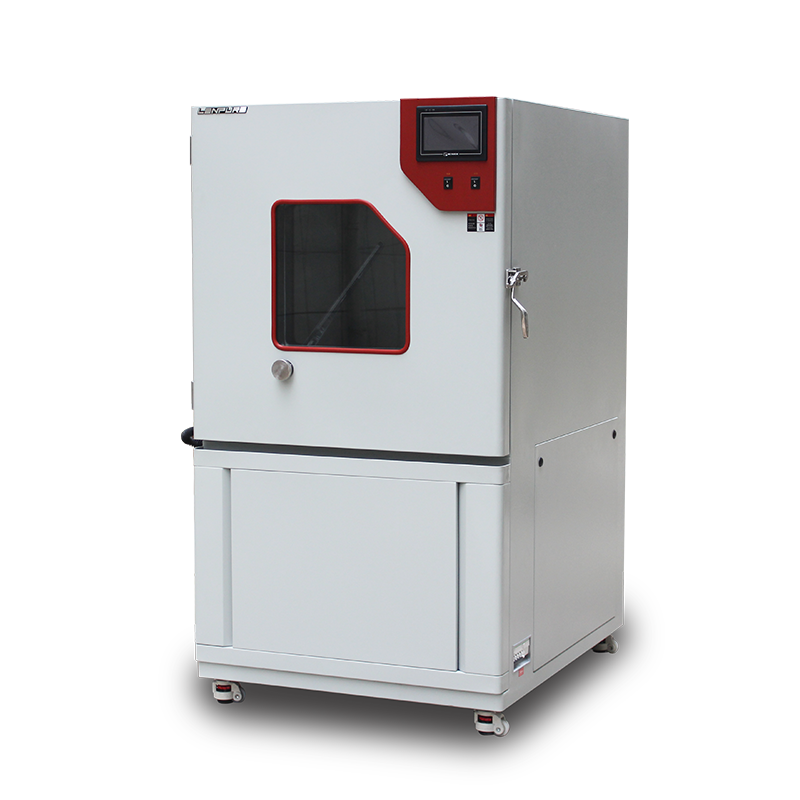
A sand and dust test chamber is the core item of equipment used to simulate desert, arid and industrial high-dust environments. The quality of its operation directly determines a product’s IP protection rating, reliability life and market-access qualification. Based on the principles of “risk anticipation, process control and result traceability”, this paper systematically lists 27 key technical details covering everything from power-on preparation to shutdown and maintenance, providing laboratory staff, third-party inspection bodies and manufacturing engineers with practical, actionable guidance.
II. Systematic pre-use checks
2.1 Electrical safety verification
a) Rated supply: three-phase five-wire AC 380 V ±10 %, 50 Hz ±0.5 Hz; PE conductor impedance ≤ 4 Ω.
b) Stabiliser: external AVC stabiliser (accuracy ≤ ±2 %) to prevent compressor or vibrator trip due to voltage sag.
c) Insulation resistance: measure phase–earth and phase–phase with a 500 V megger; ≥ 20 MΩ cold, ≥ 5 MΩ hot.
d) Residual-current device: type B RCD, 30 mA, trip time ≤ 100 ms, preventing micro-shorts caused by conductive dust films.
2.2 Air supply and exhaust
a) Compressed air: dew-point ≤ –40 °C, particles ≤ 0.1 µm, oil mist ≤ 0.1 mg/m³, pressure 0.5–0.7 MPa.
b) Exhaust: φ110 mm port on chamber roof, connected to HEPA + bag filter in series; terminal velocity ≥ 15 m/s, ensuring dust concentration ≤ 0.15 mg/m³ at 2 m (meeting GB 16297 un-organised-emission limit).
2.3 Talc pre-treatment
a) Sieving: dry-sieved through 200 mesh (75 µm), residue ≤ 2 %.
b) Drying: 105 °C ±2 °C for 4 h, moisture ≤ 0.5 %.
c) Re-use limit: same batch used ≤ 20 cycles to prevent moisture absorption and agglomeration.
III. Sample mounting and fixture design
3.1 Load cross-section
Total projected sample area ≤ 50 % of working-section area; any single direction ≤ 70 % to avoid bypass flow.
3.2 Fixture material
6061-T6 aluminium alloy or SUS304, anodised or brushed; no organic coatings that could shed and contaminate the dust.
3.3 Earthing
Fixture connected to chamber wall equipotential bond; earth resistance ≤ 1 Ω to prevent electrostatic dust attraction.
IV. Parameter setting and calibration
4.1 Temperature
a) Set-points: 23 °C, 55 °C, 85 °C; calibrated with external Pt100 sensors (±0.15 °C) in 9-point grid per GB/T 5170.2.
b) Heating rate: ≤ 1 °C/min to avoid instantaneous seal distortion.
4.2 Dust concentration
Laser turbidity meter (0–10 g/m³, linearity ±2 %), sampling 50 mm upwind of specimen; target 2 kg/m³ ±0.2 kg/m³, logged every 30 min; auto refill if drift > 5 %.
4.3 Air velocity
Vertical velocity 1.5 m/s ±0.2 m/s, calibrated with hot-wire anemometer at specimen geometric centre.
4.4 Vibration motor
Eccentricity 2 mm, 50 Hz, duty 5 s ON / 55 s OFF to keep the hopper clear yet avoid weld fatigue from continuous resonance.
V. In-test monitoring
5.1 Key sequence
a) 0–5 min: soft-start fan → dust pre-circulation → concentration OK.
b) 5 min–T: test dwell; log T, RH, concentration, velocity every 10 min.
c) T–T+5 min: heating off, fan speed down, vibrator runs 2 min to clear dust.
d) After T+5 min: main power off, open relief valve, wait 10 min before door opening.
5.2 Abort criteria
Stop immediately if:
— chamber temperature deviates > ±3 °C;
— dust concentration < 1.5 kg/m³ or > 2.5 kg/m³;
— vibrator current > 120 % rated;
— exhaust filter differential ≥ 1 500 Pa.
VI. Test termination and sample recovery
6.1 Settling
Keep door closed 15 min after stop; allow airborne dust to settle until concentration ≤ 0.02 g/m³.
6.2 Sample cleaning
a) Work in negative-pressure bench; blow with 0.2 MPa oil-free nitrogen top-down; no brushes that could scratch.
b) Gravimetric check: mass increase ≤ 10 mg deemed seal-tight.
c) Functional check: after 2 h recovery at 23 °C ±2 °C, 45 %–55 % RH, re-test insulation, sealing, optical and electrical performance.
VII. Cleaning and maintenance
7.1 Daily
— Vacuum chamber floor residues.
— Wipe viewing window and seals with ethanol.
— Check vibrator bolt torque (8.8 N·m).
7.2 Weekly
— Remove fan impeller, blow clean; replace any missing balance weights.
— Calibrate dust sensor zero & span.
— Drain compressor reservoir.
7.3 Yearly
— Replace HEPA and pre-filters.
— Entrust accredited body to re-calibrate temperature, velocity, concentration.
— Inspect contactors and relays; replace if outside tolerance.
VIII. Personnel protection and environmental controls
8.1 PPE
KN95 mask, goggles, anti-static gloves; prolonged inhalation of talc may cause pneumoconiosis—limit exposure to 2 h per entry.
8.2 Room conditions
Ambient RH ≤ 65 % to prevent dust clumping; conductive floor with earth ≤ 10 Ω; 5 kg ammonium-phosphate extinguisher provided for electrical fires.
IX. Documentation and traceability
9.1 Raw records
Include test order, pre-use checklist, calibration certificates, run curves, alarm screen shots, specimen photos (before & after).
9.2 Data retention
Electronic records ≥ 10 years, paper ≥ 3 years, ensuring traceability to every gramme of talc and every temperature fluctuation.
The reliability of a sand and dust test chamber is “30 % hardware, 70 % operation”. Only by integrating electrical safety, dust characteristics, airflow organisation, sequence control and personnel protection into a standardised management system can measurement repeatability be kept within 3 %, providing solid technical backing for R&D, quality arbitration and international trade. Each laboratory should compile its own Sand and Dust Test Operating Instruction based on these clauses and its specific chamber model, and review its effectiveness annually for continuous improvement.
25.03

Copyright © 2025 Shanghai Linpin Instrument Co., Ltd Copyright
| ICP Number:Shanghai ICP Record No. 12029585-7
| Sitemap


 EN
EN
 中文
中文 Pусский
 Tiếng Việt
 ภาษาไทย
 پاکستانی زبان