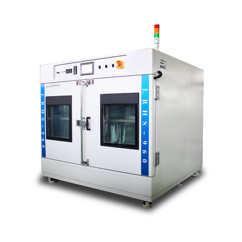
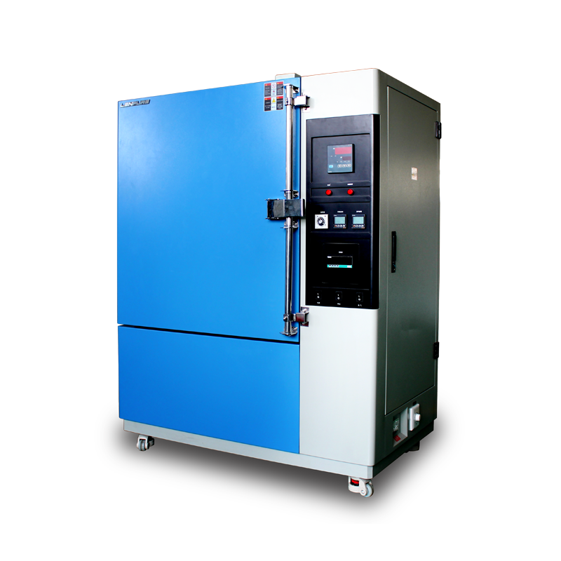
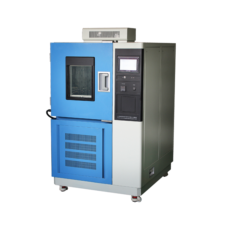
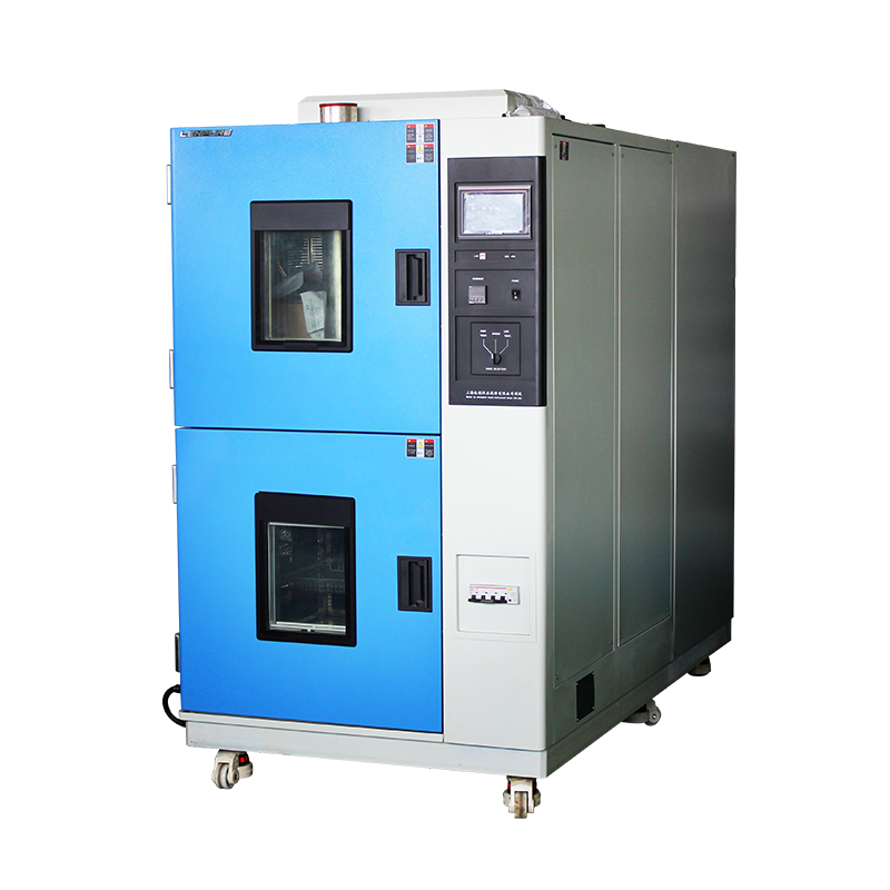
Although both thermal-shock and steady-state temperature/humidity tests fall under the umbrella of “weathering verification”, they differ fundamentally in physical modelling, control logic and safety strategy. A Thermal Shock Chamber (TSC) uses “transient temperature gradients” as the core variable, forcing specimens to fail by thermal stress through severe zone-to-zone transfers. The data generated support reliability engineering in aerospace, automotive electronics, semiconductor packaging and new-energy batteries. This paper formally and objectively expounds the six differentiated features of modern TSCs.
Feature 1 – Ultra-fast Transfer and Recovery
2.1 Definitions
Per IEC 60068-2-14, MIL-STD-810H and GB/T 2423.22, “transfer time” is the interval needed to move the test zone from +180 °C to –65 °C or vice-versa; leading machines achieve ≤15 s. “Recovery time” is the period required for the specimen zone to reach and stabilise within ±2 °C of the target; top-tier levels are ≤5 min.
2.2 Enabling Technologies
a) Binary cascade refrigeration: an R-404A high-stage precools the R-23 low-stage, with CO₂ booster or auto-cascade to –85 °C evaporating temperature, guaranteeing ≤15 s precondition.
b) High-speed dampers + basket drive: two-zone (basket) types employ a servomotor and linear encoder; PID synchronises damper opening (≤0.3 s) and basket motion. Three-zone (static) types use independent air valves with double-layer insulation; blade opening ≥85°.
c) Intelligent pre-conditioning algorithm: 3 min before cycle end the controller over-drives each zone to set-point +10 °C; on transfer command, reverse compensation eliminates overshoot and shortens recovery.
Feature 2 – Modular, Independent Dual-zone Control
3.1 Mechanical Layout
Both two- and three-zone versions adopt “dual shell + independent insulation”. A glass-fibre thermal bridge (λ ≤0.022 W m⁻¹ K⁻¹) separates the zones, preventing condensation with 200 °C differential.
3.2 Control Loops
Each zone owns heaters, evaporators, fans and sensors, forming two isolated closed loops. Single-point failure in one zone does not abort the test.
3.3 Feed-through Design
A φ50 mm stainless flange on the roof houses a PTFE conical gland tolerating –80 °C to +200 °C; stepped silicone O-rings give IP55, allowing high-voltage looms, fibre optics or RF coax to enter without leakage.
Feature 3 – Multi-layer Safety Interlocks
4.1 Hardware Interlock
Fan, basket drive, damper actuator and door limit switch are serially wired. Door opening instantly cuts power to fan and drive; dampers stay closed, preventing hot effluent or cold refrigerant escape.
4.2 Software Interlock
A “safety word” bit in the PLC forces the system into HOLD when the door opens; heating and cooling outputs are latched off. Event logs (time-stamp, temperature, operator ID) satisfy GAMP 5 traceability.
4.3 Redundant Protection
An independent snap-action over-temperature protector (STB) with a separate K-type thermocouple trips at set-point +10 °C, de-energising SSRs without software intervention, complying with IEC 61010-1.
Feature 4 – Fully Programmable, Intelligent O&M
5.1 Program Framework
Built on IEC 61131-3, the controller mixes ladder diagram and structured text. A built-in “shock template library” combines five stages—hot dwell, cold dwell, transfer, recovery, soak—supporting up to 9 999 cycles per segment.
5.2 Auto-tuning
A fuzzy-PID hybrid continuously identifies slope, overshoot and steady-state error. If recovery exceeds 5 min for three consecutive cycles, the system offers an auto-tuning wizard to re-match PID coefficients.
5.3 Remote Maintenance
Dual RJ45 and RS-485 ports with Modbus-TCP/RTU integrate into plant SCADA. VPN-encrypted tunnels allow authorised engineers to upgrade firmware, diagnose alarms and apply electronic signatures, meeting FDA 21 CFR Part 11.
Feature 5 – Binary Cascade Air-cooled Refrigeration
6.1 Thermodynamic Cycle
High-stage R-404A and low-stage R-23 form a reverse Stirling cycle. After first compression, inter-cooling, second compression and dual expansion, theoretical COP reaches 0.72 at –65 °C.
6.2 Key Components
a) Tecumseh hermetic compressor: DU bearings, low oil throw (≤1.5 %), extending heat-exchanger life.
b) Plate heat-exchanger: 316L vacuum-brazed, 0.42 m² area, U ≥6 500 W m⁻² K⁻¹.
c) Electronic expansion valve (EEV): stepper-motor driven, 0.1 % resolution, cascaded with evaporator temperature to hold fluctuation within ±0.3 °C.
6.3 Air-cooled Condenser
Aluminium fins on copper tubes, 2.1 mm fin pitch, face velocity 3.5 m s⁻¹; condensing temperature ≤45 °C. Variable-frequency axial fans auto-adjust with ambient, noise ≤68 dB(A) at 1 m.
Feature 6 – Multi-layer Composite Insulation
7.1 Materials
Inner layer: high-density polyurethane foam, 48 kg m⁻³, closed-cell ratio ≥95 %, λ =0.019 W m⁻¹ K⁻¹.
Outer layer: 10 mm silica-aerogel blanket with aluminium-foil reflector, blocking radiative heat; surface rise ≤ambient +5 °C.
7.2 Thermal-bridge Suppression
All penetrations—heater flanges, sensor wells, feed-throughs—use “PTFE sleeve + dual O-ring” geometry, cutting bridge area to 30 % of conventional designs and eliminating shell condensation.
7.3 Energy Verification
Under +180 °C/–65 °C cycling and 25 °C ambient, steady-state power ≤4.8 kW, 18 % more efficient than single-layer insulation, meeting GB/T 18430.1 minimum energy-performance requirements.
Conclusion
By integrating ultra-rapid transfer, independently controlled dual zones, multiple safety interlocks, intelligent programming, high-efficiency cascade refrigeration and composite insulation, the modern thermal shock chamber establishes a formidable technical barrier in transient thermal-stress simulation. These differentiated designs not only improve test efficiency and data accuracy but also provide a dependable failure-analysis platform for high-end manufacturing. For further information on test-standard selection, customisation or metrology services, please call the technical hotline +86-400-066-2888 for one-to-one consultation with a qualified engineer.
25.03


Copyright © 2025 Shanghai Linpin Instrument Co., Ltd Copyright
| ICP Number:Shanghai ICP Record No. 12029585-7
| Sitemap


 EN
EN
 中文
中文 Pусский
 Tiếng Việt
 ภาษาไทย
 پاکستانی زبان