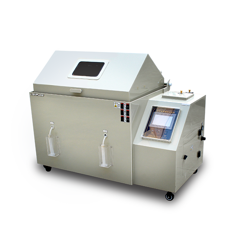
The salt fog chamber is the core instrument for evaluating the corrosion resistance of materials and protective coatings. Its measurement repeatability and reproducibility are directly affected by installation quality. Any deviation during on-site deployment may introduce systematic errors over subsequent hundreds or even thousands of hours of continuous testing, leading to data drift, misjudgement of sample failure, and increased shutdown maintenance costs. Therefore, installation must be included in the “first-inspection” regime and managed under a three-level quality control protocol of “plan – verify – confirm”. Based on GB/T 10587, GB/T 2423.17, ASTM B117 and ISO 9227, and integrating technical manuals of major domestic manufacturers, this document systematically reviews the key control points during installation and provides executable technical guidance for laboratories, inspection bodies and production sites.
II. Installation Environment Requirements
A. Space Layout
Site-selection principle: give priority to an independent environmental simulation room; if restricted, place the chamber inside the plant, away from vibration sources (presses, air compressors, large motors) and strong electromagnetic interference sources (high-frequency hardening machines, welding stations).
Floor load: the fully loaded mass of the equipment (including saturator, heating water tank, specimen racks and 50 L salt solution) is usually ≥ 300 kg. Ensure a static floor load ≥ 500 kg/m² and level the floor with a spirit level; longitudinal and transverse levelness ≤ 0.5 mm/m.
Clearances:
Rear ≥ 600 mm for condenser heat dissipation, circuit maintenance and saturator water filling;
Left/right sides ≥ 400 mm to avoid thermal radiation affecting adjacent equipment;
Front door area ≥ 1 000 mm to allow specimen loading/unloading and nozzle maintenance.
Ventilation & sunshine: room air-exchange rate ≥ 6 ACH. When organic salt fog (CASS, ASS) tests are run, provide a corrosion-resistant exhaust hood. Direct sunlight on the cabinet is forbidden to prevent ageing of PVC, PPS and other polymer parts.
B. Ambient Parameters
Temperature: 15 °C – 30 °C; relative humidity: ≤ 75 %RH; atmospheric pressure: 86 kPa – 106 kPa; no flammable, explosive or corrosive gases; dust concentration ≤ 0.2 mg/m³.
III. Technical Specifications for Utility Interfaces
A. Power Supply System
Rated voltage: AC 220 V ± 10 % / 50 Hz or AC 380 V ± 10 % / three-phase five-wire system, exactly as indicated on the nameplate.
Protective earthing: independent PE conductor, yellow-green, cross-section ≥ 2.5 mm²; earth resistance ≤ 4 Ω.
Residual-current protection: 30 mA residual-current circuit-breaker, trip time ≤ 0.1 s, on a separate branch from the laboratory main switch to avoid nuisance tripping.
Voltage stabilisation & isolation: if mains variation > ± 10 %, add a 5 kVA on-line UPS or precision voltage regulator to prevent heater and PLC damage by over-voltage.
B. Compressed-Air System
Air quality: comply with ISO 8573-1:2010 class [2:4:2], i.e. solid particles ≤ 0.5 µm, oil content ≤ 0.1 mg/m³, pressure dew point ≤ 3 °C.
Supply pressure: stabilise at 0.7 MPa – 0.8 MPa before the chamber, then reduce to 0.1 MPa – 0.2 MPa by a two-stage regulator for the nozzle; during testing the pressure must not fall below 0.3 MPa (3 kgf/cm²).
Piping material: Φ 8 mm × 1 mm transparent PU tube or 316 L stainless-steel tube; galvanised steel is forbidden to prevent Zn²⁺ contamination of the salt solution.
Quick couplings: PC8-02 self-locking type, rated 1.5 MPa, ≥ 500 connect/disconnect cycles, ensuring maintenance efficiency.
Continuous air supply: for test cycles > 72 h, provide a ≥ 100 L air receiver plus refrigerant dryer to avoid pressure pulsation caused by frequent compressor start/stop.
C. Water Supply System
Water quality: de-ionised or distilled water with conductivity ≤ 5 µS/cm must be used for the saturator, seal trough and heating tank; nozzle rinsing may use laboratory grade-2 water (GB/T 6682).
Pressure & flow: inlet 0.1 MPa – 0.3 MPa; automatic make-up line fitted with a 40 mesh Y-strainer and a non-return valve to prevent impurities and siphoning.
Tank capacity: external 20 L PE tank with level alarm and low-level automatic shutdown.
IV. Emission & Environmental Requirements
A. Drain Line
Material: acid/alkali-resistant PVC-U, OD 32 mm, wall 2.0 mm, solvent-cement joints.
Gradient: horizontal section ≥ 3 %; “negative slope” and U-traps are forbidden to prevent salt-solution back-flow.
End-of-line treatment: discharge into laboratory neutralisation pit; adjust pH to 6.5 – 8.5 with NaOH before entering factory sewer. If copper salt (CASS) is used, add a Na₂S precipitation tank; Cu²⁺ ≤ 0.5 mg/L before discharge.
B. Exhaust Line
Material: same as above, Φ 50 mm PVC-U, temperature ≤ 60 °C.
Routing: chamber top mist outlet → local exhaust hood → corrosion-resistant centrifugal fan → outdoor vertical stack; outlet ≥ 1 m above roof with weather-cap.
Back-flow prevention: horizontal section ≥ 2 % gradient, outdoor end lower than indoor; if necessary, fit a PVC non-return valve.
Mist recovery: a “salt-mist catcher” (multi-stage PP packing + demister pad) is recommended; collection efficiency ≥ 90 % to reduce NaCl particle corrosion of roof steelwork.
C. Sealing & Leak Test
All pipe joints use EPDM corrosion-resistant O-rings plus PVC solvent cement double seal. After installation, conduct a 15 kPa pressure-hold test; pressure drop ≤ 0.5 kPa in 10 min is acceptable.
V. On-Site Commissioning & Acceptance
A. No-Load Run
Temperature deviation: 35 °C ± 2 °C (neutral salt fog). Calibrate with a certified multi-point logger, nine-point layout; deviation ≤ ± 1 °C.
Salt-fog settlement: 80 cm² funnel method, continuous spraying 24 h; average settlement 1.0 – 2.5 mL/h; four-point spread ≤ 0.4 mL/h.
Pressure stability: automatically record supply-pressure curve; fluctuation ≤ ± 0.01 MPa.
B. Loaded Run
Place standard steel panels (Q235, Ra ≤ 0.8 µm); after 48 h, corrosion grade ≥ grade 4 of GB/T 6461-2002, and difference between upper and lower samples ≤ 1 grade, proving spray uniformity.
C. Documentation
Commissioning report, earth-resistance record, water-quality certificate, leak-test record and training attendance sheet are filed and kept ≥ 6 years.
VI. Common Installation Defects & Corrective Actions
Defect: drain pipe laid horizontal without gradient, causing solution back-flow after shutdown and heater corrosion perforation.
Correction: dismantle horizontal section; re-route with ≥ 3 % gradient and add a transparent sight tube for inspection.
Defect: air compressor not fitted with refrigerant dryer; moist air causes frequent nozzle blockage.
Correction: add refrigerated dryer + fine filter; drain condensate weekly; replace nozzle with Si₃N₄ ceramic to triple service life.
Defect: exhaust pipe passes directly through wall to outdoors without rain protection; rain water back-flow causes inner tank corrosion.
Correction: fit 45° elbow + weather-cap on outdoor end; add a drain tee at the lowest point for periodic manual discharge of condensate.
VII. Personnel Training & Maintenance Pre-Conditions
After installation, the manufacturer’s engineer shall train operators, maintenance staff and safety officers on site; 100 % pass in the assessment is required before hand-over.
Establish a three-level (daily, weekly, monthly) check list covering: water level, pressure, nozzles, O-rings, pipe leakage, earth continuity.
Spare-parts store: 2 nozzles, full set of EPDM O-rings, 5 m PU tube, 5 each of 2 A / 10 A fuses, ensuring fault response time ≤ 4 h.
VIII. Conclusion
Installation quality is the first gateway to guaranteeing the metrological characteristics and service life of a salt fog chamber. Strictly following the four control modules of space layout, utilities, emission & environment, and commissioning & acceptance, supplemented by full-process records and risk-prevention thinking, can reduce the potential failure rate by more than 70 % and provide a stable, reliable and traceable test environment for subsequent material corrosion evaluation. It is hoped that every laboratory and on-site engineer will use this specification as a blueprint, refine the work instruction in line with actual conditions, and achieve the goal of “well installed, accurately measured, long-lasting”.


25.03
25.06

Copyright © 2025 Shanghai Linpin Instrument Co., Ltd Copyright
| ICP Number:Shanghai ICP Record No. 12029585-7
| Sitemap


 EN
EN
 中文
中文 Pусский
 Tiếng Việt
 ภาษาไทย
 پاکستانی زبان