Product reliability is no longer governed solely by design rules and manufacturing precision; it is equally decided by a product’s ability to survive sudden climatic extremes. Among all environmental stressors, rapid temperature change is the single most frequent root-cause of field failures in electronic components, automotive assemblies, and aerospace hardware. The thermal-shock test chamber (TSC) was developed specifically to reproduce “high–low–high” transient cycles under laboratory conditions. Modern TSCs can accomplish temperature excursions exceeding ±100 °C within a few tens of seconds, forcing latent material and process defects to manifest themselves in hours rather than years. The quantitative data generated are used to refine designs, perform component screening, and demonstrate compliance with international standards.
Equipment Taxonomy and Structural Features
Commercial TSCs are divided into two principal families that differ fundamentally in the way the specimen is exposed to the extreme zones.
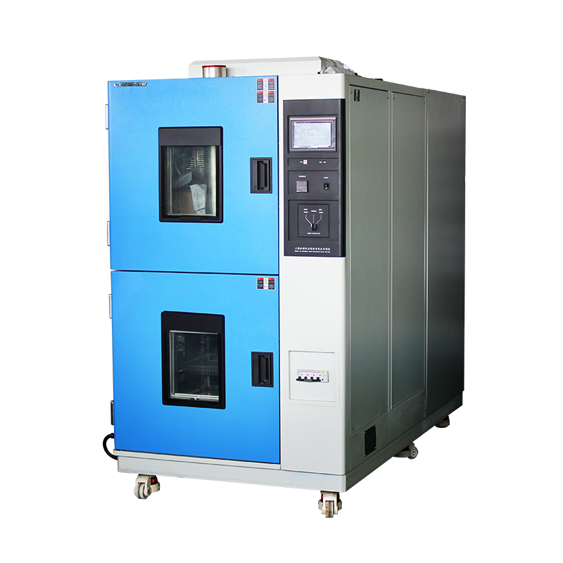
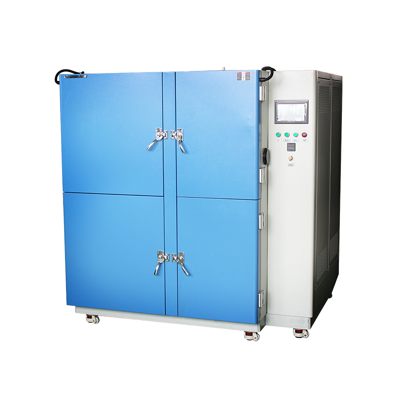
2.1 Two-zone (basket-transfer) construction
A high-temperature compartment and a low-temperature compartment are arranged side-by-side; a sealed pneumatic basket shuttles the load between them. Transfer time is typically ≤10 s, and temperature recovery is completed within 5 min. The steep gradient and compact footprint make the two-zone architecture attractive for small, rugged parts such as semiconductor dies or chip-scale packages. The drawback is mechanical stress imposed on the specimen by the basket movement, and the need for extremely reliable shuttle mechanics. Delicate or cable-connected assemblies are therefore excluded.
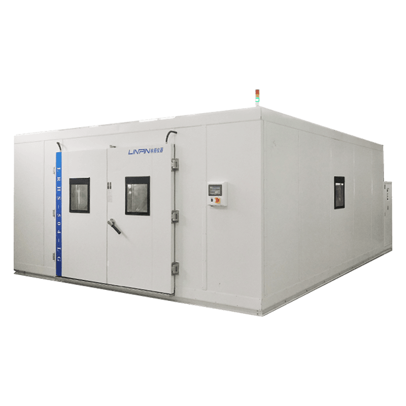
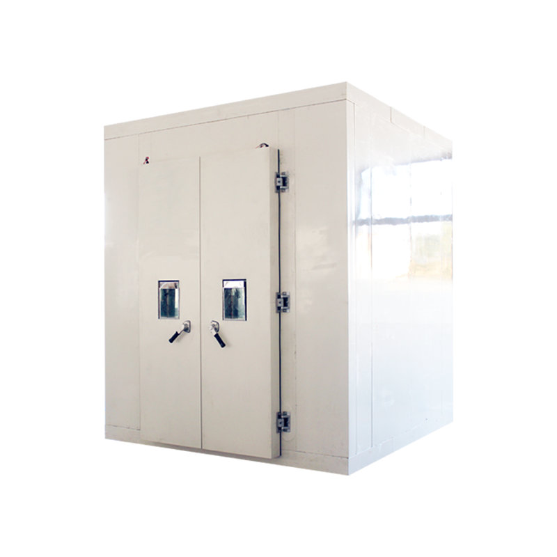
2.2 Three-zone (valve-switching) construction
A third, independently controlled test compartment is added. High- or low-temperature air is injected into this zone by high-speed pneumatic valves; the specimen remains stationary throughout the test. Valve switching is achieved in ≤5 s, and temperature recovery is usually ≤3 min. Because no physical transfer occurs, large, fragile, or harnessed articles—complete battery packs, avionics black boxes, or medical devices—can be tested safely. Energy consumption is marginally higher because of the additional air-handling hardware, but repeatability and operator safety are markedly improved.
Key Performance Specifications
Temperature range: –75 °C to +220 °C (extendable to –100 °C with liquid-nitrogen assist)
Transition time: ≤30 s (MIL-STD-810H demands ≤1 min)
Temperature recovery: ≤5 min (IEC 60068-2-14 Nb)
Spatial deviation: ≤±2 °C (nine-point unloaded survey)
Programmable cycles: 1–9,999, with multi-slope soak and ramp control
Data logging: 1 s interval; Ethernet, USB, and MES interfaces; 21 CFR Part 11 electronic-signature compliance
Core Sub-systems
Refrigeration: Cascade or auto-cascade circuits using R404A/CO₂ or R23/R508B. A fully hermetic scroll compressor serves the high stage; a semi-hermetic piston machine handles the low stage. Oil separators and level-regulated return circuits guarantee oil-free suction at –75 °C and eliminate liquid slugging.
Heating: Ni-Cr finned elements regulated by zero-cross SSRs under PID control deliver ramp rates up to 30 °C min⁻¹. Heaters are interlocked with the refrigeration circuit to prevent positive-pressure overlap that could damage the compressor.
Airflow management: Two-zone chambers employ vertical down-draft ducts at 8–10 m s⁻¹, holding basket ΔT ≤1.5 °C. Three-zone models use lateral air jets at 15–20 m s⁻¹ to generate turbulent heat transfer and maximize uniformity.
Control & telemetry: A Siemens S7-1200 PLC supervises all functions; a 7-inch colour HMI contains templates for GB/T 2423, IEC, MIL, JIS, IPC-TM-650, and 200+ other standards. Remote monitoring via Ethernet and smartphone push-alerts are standard.
Safety: Sixteen-fold protection covers overtemperature, overload, phase reversal, earth-leakage, over/under-voltage, oil deficiency, fan stall, and valve malfunction. A CO₂ or N₂ fire-suppression port is fitted as standard to meet UL 94 V-0 flammability requirements.
Industrial Application Matrix
Semiconductor & electronic packaging: ICs, QFNs, BGAs, and wafer-level packages are subjected to –55 °C↔+150 °C for 1,000 cycles to reveal solder-ball fatigue, delamination, and electromigration.
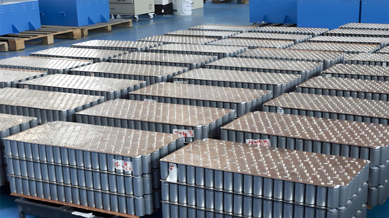
Automotive electronics: ECUs, sensors, and lithium-ion modules are tested to ISO 16750-4 (–40 °C↔+85 °C) to verify cold-crank capability, sealant degradation, and joint integrity.
Aerospace & defence: Connectors, fibre-optic gyros, and satellite power converters follow MIL-STD-883K Method 1010.9 (–65 °C↔+150 °C, 200 cycles) to generate reliability-growth documentation.
Advanced materials: Carbon-fibre composites, ceramic substrates, and 5G high-frequency PCBs are evaluated for resin–fibre debonding, micro-via expansion, and dielectric drift.
Medical electronics: Implantable pacemakers and imaging detectors undergo –30 °C↔+70 °C shocks per IEC 60601-1-11 to ensure functionality during emergency transport.
Test Workflow and Data Interpretation
A typical sequence is: specimen pre-conditioning → initial electrical test → programme parameter set-up → cyclic exposure → interim measurements → final electrical/dimensional/ mechanical inspection → failure analysis.
Failure criteria:
a) Electrical parameter drift >10 % of specification
b) Visual evidence of cracking, blistering, or delamination
c) Seal-leak rate >1×10⁻⁶ Pa m³ s⁻¹
d) Mechanical-strength loss >20 %
Weibull analysis of cycles-to-failure yields the characteristic life η and shape parameter β, which feed Arrhenius or Coffin–Manson acceleration models to extrapolate a ten-year field failure rate.
Equipment Selection, Installation, and Maintenance
Selection: Semiconductor dies favour the two-zone architecture; larger or cable-harnessed articles require the three-zone approach. Heat-dissipating or powered loads need additional capacity margin.
Installation: Ambient 5–35 °C, RH ≤85 %, well ventilated, 1 m service clearance; 3-phase 5-wire 380 V ±10 %, total harmonic distortion ≤5 %.
Maintenance: Every 400 h inspect cascade pressures and oil colour; every 1,000 h replace dryer filters; every 2,000 h calibrate temperature sensors and anemometers; replace valve seals every two years to prevent internal leakage and temperature overshoot.
Metrology: Follow JJF 1101-2019 using a nine-point survey; recalibrate annually to ensure data validity and traceability.
Future Directions
Green refrigeration: Trans-critical CO₂ and low-GWP mixed refrigerants (<150) to comply with the EU F-Gas regulation.
Smart diagnostics: Digital-twin algorithms predict compressor remaining life and evaporator frost thickness, enabling predictive maintenance.
Combined stressing: Four-in-one systems integrate thermal shock with vibration, humidity, and electrical load to replicate real-world mission profiles.
Miniaturisation: Chip-level micro-chambers with ≤0.5 L volume and 120 °C min⁻¹ ramp rates for 24/7 in-line wafer-fab monitoring.
Low-noise design: Inverter-driven scroll compressors and acoustic enclosures reduce overall noise to ≤58 dB(A), allowing installation in mixed office/laboratory areas.
Conclusion
Once a simple temperature-cycling tool, the thermal-shock test chamber has evolved into an integrated platform that combines precision thermal control, remote operation, and full data compliance. A clear understanding of the structural differences between two-zone and three-zone architectures, rational selection of transition rates and dwell times, and correlation of test data with physics-of-failure models not only uncover product weaknesses early but also dramatically reduce field failure rates and associated warranty costs. Driven by carbon-neutrality mandates and smart-manufacturing initiatives, thermal-shock technology will continue moving toward higher efficiency, lower environmental impact, and deeper integration with multi-physics reliability verification, thereby safeguarding the next generation of high-value electronic and electromechanical systems.


Copyright © 2025 Shanghai Linpin Instrument Co., Ltd Copyright
| ICP Number:Shanghai ICP Record No. 12029585-7
| Sitemap


 EN
EN
 中文
中文 Pусский
 Tiếng Việt
 ภาษาไทย
 پاکستانی زبان