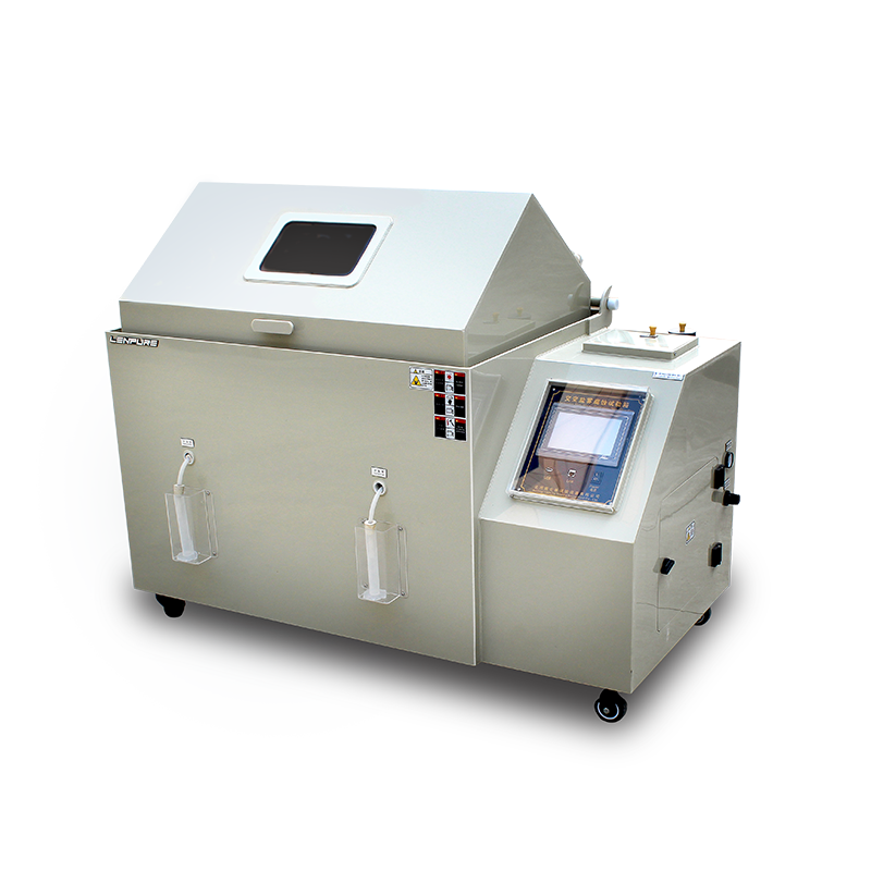
Salt-spray corrosion testing is one of the most frequently used and fastest accelerated methods for evaluating the corrosion resistance of materials and their protective coatings. In a test chamber a salt solution is atomized by compressed air into a uniform fog that is continuously or intermittently sprayed onto specimens in a sealed, temperature- and humidity-controlled space. In this way the corrosive medium fully contacts the metal surface and, within a short time, reproduces the corrosion morphology and mass-loss behaviour that the material would exhibit in a marine or industrial atmosphere. Depending on solution chemistry and pH, salt-spray tests are divided into three mainstream variants—neutral salt-spray (NSS), acetic-acid salt-spray (AASS) and copper-accelerated acetic-acid salt-spray (CASS)—covering general platings, decorative chromium and Cu–Ni–Cr multilayer systems respectively. Although the procedure appears straightforward—“spray–collect–dry–inspect”—round-robin programmes worldwide show that the mass-loss and time-to-first-rust of identical specimens can differ by more than 30 % between laboratories, chambers or even shifts. These deviations are not random but stem from systematic errors that propagate through the entire “man–machine–material–method–environment” chain. The following five-dimensional analysis identifies the critical variables and offers technical guidance for establishing traceable, reproducible and auditable salt-spray data.
Uncertainty contributed by the specimen itself
1.1 Machining stress and surface topography
Residual tensile stress introduced by turning, stamping or grinding can markedly lower the critical pitting potential. For the same steel grade, wet-ground and dry-ground surfaces may differ in time-to-rust by a factor of 2–3. ISO 9227 requires specimen edges to be rounded or masked; otherwise the intensified electric field at sharp edges initiates premature corrosion.
1.2 Pre-existing corrosion products and contamination films
A thin moisture film formed on steel during storage acts as a cathodic site and accelerates anodic dissolution of the surrounding metal. Conversely, cutting-oil residues on aluminium hinder oxygen depolarisation and retard corrosion. Both situations shift the “test starting point”.
1.3 Mounting angle and galvanic coupling
VDA 233-102 states that a tilt of 15°–30° to the horizontal gives maximum fog deposition. If the specimen is parallel to the salt-fall direction, droplets drain away, the local Cl⁻ concentration falls and the corrosion rate drops by 15–20 %. When dissimilar metals are clamped together, a potential difference of up to 0.6 V can be established; the galvanic current density is an order of magnitude higher than the free corrosion rate, so the result no longer represents the intrinsic resistance of the material.
Drift of test-environment parameters
2.1 Salt-fall rate
The standard specifies 1.5 ± 0.5 mL h⁻¹ per 80 cm² horizontal collector. A nozzle-orifice wear of 0.1 mm, oil in the compressed-air line or a 0.02 MPa pressure fluctuation can shift the rate outside this band; when the rate rises to 2.2 mL h⁻¹ the mass-loss of Q235 steel increases by 28 %.
2.2 Temperature uniformity
IEC 60068-2-11 requires 35 ± 2 °C throughout the working volume. With a poor heater layout the difference between roof and floor can reach 4 °C. Each 1 °C rise raises the chloride diffusion coefficient by ~3 % and the anodic dissolution current density by 6–8 %, amplifying the final result exponentially.
2.3 Humidity and secondary evaporation
After spraying, the relative humidity inside the chamber must remain ≥95 % to keep the electrolyte film continuous. If a gasket ages and outside air leaks in, “wet–dry” cycling occurs, the corrosion-product film cracks repeatedly and the mass-loss is more than 40 % higher than under constant wetness.
2.4 Solution pH and impurities
For NSS the pH must be 6.5–7.2. If the stock solution is stored in ordinary stainless steel, dissolved Fe³⁺ and Cr³⁺ can lower the pH to 6.0; the combined action of Cl⁻ and H⁺ depresses the pitting potential by ~50 mV. Tap water containing Ca²⁺ and Mg²⁺ causes nozzle blocking and a 10 % fall in spray volume; the hard salt particles also sand-blast the surface, raising the Ra by 0.2 µm and further accelerating corrosion.
Ageing of chamber hardware and auxiliary components
3.1 Nozzle geometry
After 1 000 h of operation the ovality of a ceramic nozzle can increase from 0 % to 5 % and the D50 droplet size rises from 5 µm to 8 µm. Larger droplets preferentially deposit on upper shelves, producing a “top-heavy” corrosion gradient.
3.2 Saturation (bubble) tower efficiency
Air should reach 100 % relative humidity by bubbling through a 45 °C water column. If the frit becomes fouled, bubble size increases, the mass-transfer area shrinks and the outlet air is only 80 % saturated. The subsequent flash evaporation in the nozzle lowers the local temperature by ~3 °C, salt crystallises, the orifice blocks and the fall-out rate drops 25 %.
3.3 Collection error of fall-out gauges
An ordinary glass funnel (wall thickness 1.5 mm) adsorbs 4–6 % of the salt droplets. Replacing it with a siliconed plastic funnel improves collection by ~3 %. When reading the graduated cylinder a 0.1 mL parallax error is common, equivalent to 6–7 % of the target volume.
3.4 Broken metrological chain
If temperature/humidity sensors are not calibrated annually to JJF 1076, a 0.5 °C or 2 % RH bias already exceeds the standard tolerance; a 1 kPa zero-drift in the pressure sensor changes the spray volume by 6 %. Lack of calibration labels forces operators to apply “empirical corrections” and enlarges data scatter.
Human factors and procedural shortcomings
4.1 Solution preparation and replacement
GB/T 10125 specifies 50 ± 5 g L⁻¹ NaCl. Using a top-loading balance with 0.1 g resolution gives a ±1 g weighing error in 5 L, i.e. ±2 % in concentration. After 48 h of spraying the NaCl concentration in the sump can rise to 65 g L⁻¹ because of water evaporation; continuing the test increases the corrosion rate by 12 %.
4.2 Specimen cleaning and masking
Fingerprints leave a 0.5–1 µm fatty film that raises the initial contact angle by 20° and delays rusting by ~2 h; chlorinated rubber gloves leave Cl⁻ residues that act as pitting initiators.
4.3 Spray cycle and intermediate sampling
Some laboratories adopt a “spray 2 h–dry 1 h” cycle to shorten the test. During the dry period the oxygen diffusion rate is two orders of magnitude higher and the corrosion-current peak is 1.8 times that under continuous spray, so the result is not comparable with the standard procedure.
4.4 Data reading and rounding
When rust spots are counted with a 5× instead of a 10× microscope, pits <0.3 mm are missed and the rating shifts by +0.5 level. If corrosion products are not removed in accordance with ISO 8407, the retained rust contributes 3–5 % of the apparent mass-loss.
Long-term comparability and field validation
5.1 Reference (quality-control) coupons
Two sheets of 99.9 % Zn (or CR4 steel) are included in each batch; their mass-loss must lie within ±2σ of the historical mean. If not, the run is aborted and the cause is investigated. A Shewhart control chart based on 30 consecutive batches distinguishes systematic drift from random noise.
5.2 Correlation with outdoor exposure
Accelerated salt-spray data must be quantitatively linked to atmospheric exposure. Using the “K-factor” method in ASTM G50, 24 h CASS for Q235 steel is equivalent to one year in Qingdao marine atmosphere; if a laboratory’s high fall-out rate reduces K by 20 %, the risk arises that a steel passes in the chamber but perforates in service.
5.3 Data traceability
A LIMS records solution batch numbers, sensor calibration certificates, machining maps of specimens and environmental curves, enabling “one-click auditing”. When a customer disputes a result, the entire test can be reconstructed within 30 min, minimising conflict costs.
Errors in salt-spray testing are rarely due to a single malfunction; they are the cumulative result of coupled deviations. To obtain reproducible, comparable and extrapolatable corrosion data, laboratories must convert “standard clauses” into a “control plan”: use reference coupons as the red line, set up real-time monitoring of critical intermediate variables such as fall-out rate, temperature, pH and collection efficiency; base personnel training and authorisation on rigorous SOPs covering solution preparation, specimen masking and rating criteria; and rely on metrological traceability and intermediate checks to keep sensors, cylinders and balances permanently under control. Only then can salt-spray testing move from “empirical go/no-go” to “digital quantification”, providing technical support for material development, process optimisation and quality arbitration that withstands the scrutiny of time and the market.


Copyright © 2025 Shanghai Linpin Instrument Co., Ltd Copyright
| ICP Number:Shanghai ICP Record No. 12029585-7
| Sitemap


 EN
EN
 中文
中文 Pусский
 Tiếng Việt
 ภาษาไทย
 پاکستانی زبان