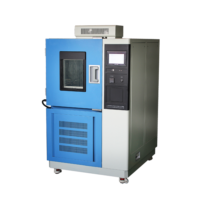
Low temperature test chambers serve as critical equipment for material low-temperature performance verification, electronic component reliability testing, and biological sample preservation. The accuracy of test results directly depends on standardized installation conditions and operational procedures. To ensure the reproducibility of test data and operational safety, operators must systematically master key technical points and prohibitions during equipment use. Based on equipment engineering specifications and long-term maintenance experience, this article elaborates on core precautions for using low temperature test chambers, providing a technical foundation for laboratory standardized management.
I. Technical Requirements and Theoretical Basis for Installation Environment
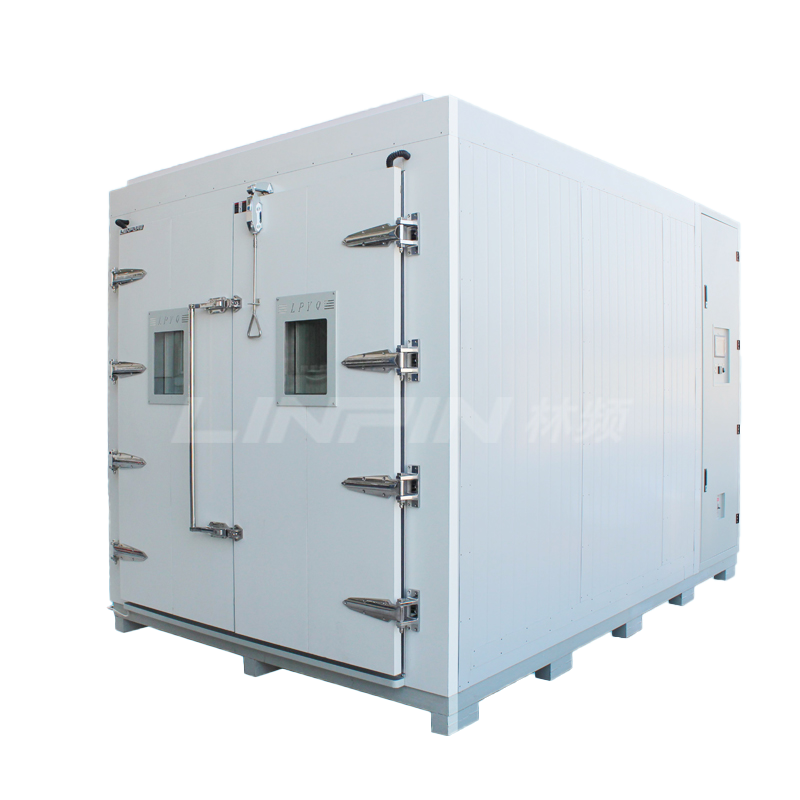
Low temperature test chambers have strict engineering requirements for installation environment. Equipment should be deployed in a well-ventilated, dry environment with relative humidity not exceeding 85%RH. This ensures condenser heat dissipation efficiency and cabinet thermal insulation performance are not compromised by environmental moisture. A clearance of not less than 30 cm must be maintained around the chamber. This requirement, based on aerodynamic principles, ensures smooth airflow at intake and exhaust ports of the forced convection system, preventing heat backflow that could cause abnormal increases in compressor discharge pressure. If equipment is placed close to walls or obstacles, fan speed must increase to maintain heat exchange efficiency, raising energy consumption by 15-20% and accelerating fan bearing wear, thereby shortening service life. Additionally, the installation floor must be solid and level, with levelness deviation controlled within 2mm/m to prevent lubrication issues and abnormal vibration from compressor operation at an incline.
II. Safety Specifications and Power Configuration for Electrical Systems
Equipment power supply configuration must strictly follow technical specifications: standard operating frequency is 50 Hz, with rated voltage of 220V single-phase AC. The total power capacity of the supply line must exceed the maximum operating power indicated on the equipment nameplate, with at least 20% safety margin reserved to avoid circuit breaker tripping or line insulation aging from voltage overload. Particular emphasis must be placed on equipping the power supply with a standardized protective grounding system, with grounding resistance not exceeding 4 ohms and grounding wire cross-sectional area not less than 2.5mm². Reliable grounding serves not only as a safety barrier against electric shock but also as a technical measure to suppress electromagnetic interference and ensure accurate transmission of weak temperature sensor signals. It is recommended to install circuit breakers with D-type tripping characteristics in the distribution circuit to withstand the instantaneous inrush current during compressor startup (which can reach 5-7 times the rated current), preventing test interruptions caused by false tripping.
III. Thermodynamic Selection Principles for Working Media
The selection of heat transfer media in low temperature test chambers directly determines temperature control accuracy and system safety. Before use, an appropriate amount of liquid medium must be injected into the chamber, with the liquid level maintained 2 cm below the workbench plate. This setting ensures the heat exchanger is fully immersed while reserving space for liquid thermal expansion, preventing medium overflow during high-temperature operation due to volume expansion. The medium type must be scientifically selected according to the target operating temperature range: When test temperature is between -5℃ and +5℃, it is recommended to use analytically pure anhydrous ethanol as the medium, with a freezing point of -114℃, ensuring low-temperature fluidity. For operating temperatures between 5℃ and 80℃, deionized water or purified water should be used to prevent mineral deposits from water on heat exchange tube walls that would affect heat transfer efficiency (a 0.1mm scale layer can reduce heat transfer efficiency by 10%). When temperature requirement is 80℃ to 90℃, a water-oil mixture (such as 30% glycerin and 70% water mixture) must be used. This medium has its boiling point increased to 105℃, reducing the risk of vaporization at high temperatures. When temperature approaches 90℃ to 100℃, high flash point heat transfer oil (such as silicone oil) should be selected for its excellent thermal stability and good insulation properties. Improper medium selection will lead to major failures such as temperature control inaccuracy, sensor corrosion, or even heating tube dry-burning.
IV. Standardized Operation Procedures for Parameter Management
Equipment operation must strictly follow established process procedures, and unauthorized personnel are prohibited from arbitrarily modifying control parameters. System parameters are divided into operating parameters (such as temperature setpoints, heating/cooling rates) and calibration parameters (such as PID control coefficients, sensor offset values). Operating parameters can be flexibly adjusted according to test standards, but original data must be recorded before changes for traceability. Calibration parameters must be corrected by professional metrology personnel after periodic verification according to JJF 1101 calibration specifications. Arbitrary changes will cause loss of control precision, and temperature deviations may exceed the allowable range of ±2℃. The only exception is when systematic errors exist between measured values and standard instrument readings, allowing correction values to be entered in the “Measurement Value Correction” menu. However, this correction process must retain written records and be signed and confirmed by the technical responsible person. It is recommended to enable parameter locking functions (usually implemented through passwords or electronic keys) to prevent test failures caused by misoperation.
V. Preventive Maintenance System and Fault Early Warning Mechanisms
In addition to the aforementioned core points, equipment use involves multiple detailed management aspects. Before daily startup, the elasticity and integrity of the door seal should be checked to prevent cold air leakage that would cause compressor overload operation. The condenser fins must be cleaned of dust weekly to maintain heat exchange efficiency. The action reliability of the over-temperature protection device should be verified monthly, as this is the final barrier to prevent sample damage and fire accidents. Equipment operation logs should record detailed start/stop times, temperature curves, and abnormal phenomena for each test, which serve as important basis for predictive maintenance. Modern intelligent equipment is equipped with fault self-diagnosis modules that can monitor compressor current, refrigerant pressure, and sensor status in real-time, providing early warnings of potential faults 72 hours in advance. In such cases, manufacturer’s technical support should be contacted promptly for remote guidance.
VI. Manufacturer Technical Support Systems and Training Services
The technical service capability of equipment suppliers is an important external resource for ensuring long-term stable operation. Regular manufacturers will dispatch senior technical service engineers to provide 2-3 days of on-site training upon product delivery, covering equipment structure principles, daily inspection items, common fault identification and emergency handling, and maintenance cycles, along with illustrated operation and maintenance manuals. After passing the training examination, operators will be issued qualification certificates to ensure they master equipment performance characteristics and prohibitions. For common equipment failure modes, such as refrigerant leakage, heating tube aging, and circulating pump abnormal noise, the training will focus on demonstrating troubleshooting steps and temporary disposal measures, enabling customers to have preliminary independent repair capabilities and avoiding minor faults causing major downtime.
As a professional manufacturer in the environmental test equipment field with decades of R&D and manufacturing experience, our company’s low temperature test chamber series adopts imported compressors and intelligent control systems, achieving temperature control accuracy of ±0.1℃ and linearly controllable cooling rates. The company provides technical services covering the entire equipment life cycle, including installation and commissioning, operation training, periodic maintenance, and software upgrades. Particularly for customers who have purchased our equipment, we promise lifetime technical support, with 7×24-hour remote diagnostic services capable of solving technical problems in real-time, and sufficient spare parts inventory ensuring fault repair time does not exceed 48 hours. High recognition from numerous industry customers has verified the comprehensive advantages of our equipment in reliability, economy, and service response. Enterprises with equipment procurement needs are welcome to visit our production base for inspection and discussion of in-depth technical cooperation, jointly promoting the technical upgrading of product quality verification systems.
In summary, the standardized use of low temperature test chambers is a systematic project involving multidisciplinary knowledge of thermodynamics, electrical engineering, and fluid mechanics. Operators should strictly comply with technical procedures, establish preventive maintenance mechanisms, and maintain close technical collaboration with equipment suppliers to give full play to equipment performance, ensure the scientific nature and authority of test data, and provide solid technical support for product R&D and quality control.

25.03


Copyright © 2025 Shanghai Linpin Instrument Co., Ltd Copyright
| ICP Number:Shanghai ICP Record No. 12029585-7
| Sitemap


 EN
EN
 中文
中文 Pусский
 Tiếng Việt
 ภาษาไทย
 پاکستانی زبان