
Service Hotline
4000-662-888
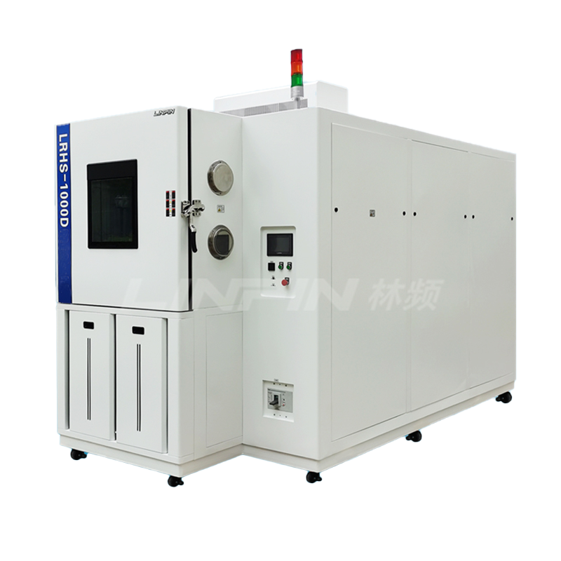
Product application:
Three-box cold and thermal shock test chambers are designed to test the endurance of material structures or composite materials under sudden exposure to extreme high and low temperatures.
They allow for the assessment of the extent to which these materials can withstand rapid temperature changes, enabling the detection of chemical changes or physical damage caused by thermal expansion and contraction within the shortest possible time.
These test chambers are essential testing equipment for industries dealing with metals, plastics, rubbers, electronics, and other materials.
Compliance with standards:
GB/T2423.1-2008
GB/T2423.2-2008
GB10592-2008
GJB150.3
GJB360A-96

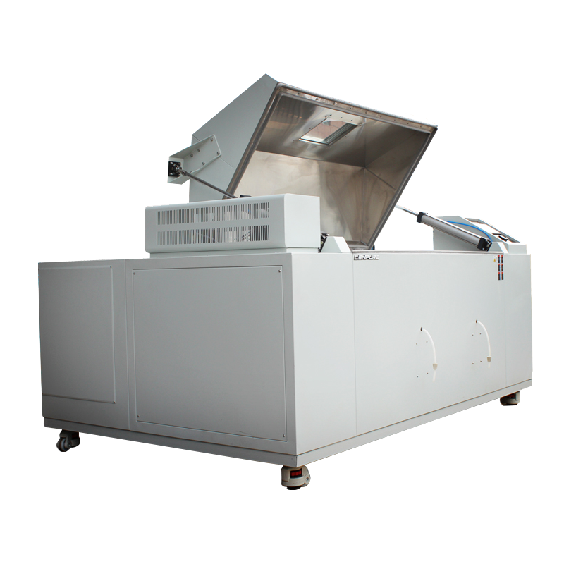
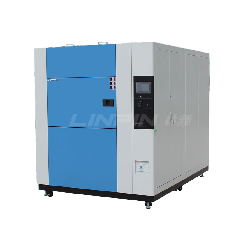
Chamber structure:
The three-box cold and thermal shock test chambers is made of high-quality (t=1.2mm) A3 steel, which is processed by a CNC machine tool. The outer shell is treated with a spray plastic coating, and the inner chamber is made of imported high-grade stainless steel (SUS304). All seams are seamlessly welded using TIG (Tungsten Inert Gas) welding.
The insulation material is polyurethane foam, which is produced through high-temperature and high-pressure foaming to integrate the inner chamber, outer shell, high-temperature zone, and low-temperature zone into a single unit.
The entire chamber of the three-box thermal shock test chamber is divided into three sections: the upper, middle, and lower parts, which correspond to the high-temperature zone, test zone, and low-temperature zone, respectively.
It features a unique heat insulation structure and heat/cold storage effect. During testing, the test object remains completely stationary, and the thermal shock test is achieved by automatically switching the hot and cold air ducts when needed.
The chamber is equipped with three original imported first-class PT100 platinum resistance temperature sensors to measure the temperatures of the high-temperature reservoir, low-temperature reservoir, and the test operation environment, respectively. These sensors are highly responsive and provide accurate measurements.
The test chamber door is interlocked with the circulation fan and the lifting mechanism to protect the operator's safety. Once the door is opened, the power supply to the circulation fan and the lifting mechanism will be automatically cut off.
The three-box thermal shock test chamber has standard wire conduits on the top, which facilitate the user to introduce sensor wires, test cables, and other types of wires into the chamber.

Control system:
The three-box cold and thermal shock test chambers is equipped with an original Japanese "Easy Control" brand temperature instrument featuring a 7-inch high-definition true color LCD touch screen.
It offers real-time monitoring capabilities, allowing users to keep track of the controller's real-time data, signal point status, and actual output status.
The instrument has the capacity for 1000 programmable segments, with each segment capable of looping through up to 999 steps, and the maximum setting for each segment is 999 hours and 59 minutes. It also includes a function for linking 10 programs.
The device can store historical data for up to 600 days (under 24-hour operation, with a recording interval of 1 minute), and it can replay and upload the historical data curves from the control system.
The equipment also features powerful network monitoring and control capabilities. This means that even if you are not physically next to the machine, you can operate and monitor it in real-time from your computer, keeping a close watch on the device's operational status.

Refrigeration system:
The three-box cold and thermal shock test chamber's refrigeration system and compressor: To ensure the test chamber's cooling rate and the requirement for the lowest temperature, this test chamber uses a dual-stage cascade air-cooled refrigeration system composed of a set of imported fully enclosed compressors from France.
The cascade refrigeration system includes a high-temperature refrigeration cycle and a low-temperature refrigeration cycle, with the connecting vessel being the evaporative condenser, which also serves the purpose of energy transfer, transferring the heat energy inside the working chamber through the two-stage refrigeration system to achieve the goal of cooling.
The design of the refrigeration system applies energy regulation technology, a proven and effective method that can ensure the normal operation of the refrigeration unit while effectively regulating the energy consumption and cooling capacity of the refrigeration system, reducing the operating costs and failure rates of the refrigeration system to a more economical state.
Refrigeration working principle: Both the high and low refrigeration cycles use the reverse Carnot cycle, which consists of two isothermal processes and two adiabatic processes.
The process is as follows: The refrigerant is adiabatically compressed by the compressor to a higher pressure, consuming work and raising the discharge temperature.
Then, the refrigerant undergoes isothermal heat exchange with the surrounding medium through the condenser, transferring heat to the surrounding medium. After that, the refrigerant undergoes adiabatic expansion and work through the valve, at which point the refrigerant temperature decreases.
Finally, the refrigerant absorbs heat isothermally from the higher temperature object through the evaporator, reducing the temperature of the object being cooled. This cycle repeats continuously to achieve the purpose of cooling.
Refrigerants: DUPONT's R404A (high-temperature cycle) and R23 (low-temperature cycle) are used.
Accessories: Expansion valve (American SPORLAN), solenoid valve (Italian CASTEL); filter (American SPORLAN); pressure controller (British American RANCO); oil separator (European and American ALCO), and other refrigeration accessories are all imported components.
| Model | Workshop size(D*W*H) mm | External Dimension(D*W*H)mm | |
| LRHS-100A-LW | 450×500×450 | 1700×1440×1900 | |
| LRHS-150A-LW | 500×600×500 | 1750×1540×2115 | |
| LRHS-225A-LW | 750×600×500 | 2200×1540×2115 | |
| LRHS-320A-LW | 800×800×500 | 2400×1740×2050 | |
| LRHS-500A-LW | 1000×900×550 | 2600×1840×2080 | |
| Impact temperature range | A:-45℃~150℃ B:-55℃~150℃ C:-65℃~150℃ | ||||
| High Temperature Chamber | RT~180℃(unloaded) | ||||
| cryostat temperature | RT~-60℃(unloaded) | ||||
| Temperature fluctuation | ≤1℃(at no load) | ||||
| temperature deviation | ±3℃(at no load) | ||||
| heating rate | From room temperature~150℃≤25min(average throughout) | ||||
| cooling rate | From room temperature~-60℃≤50min(average throughout) | ||||
| Temperature recovery time | ≤5min | ||||
| Time Setting Range | 1~60000M | ||||
| test hole | For use with external test power or signal cables | ||||
| Outer case material | High quality A3 steel plate electrostatic spraying | ||||
| Inner box material | Imported high-grade stainless steel SUS304 | ||||
| Insulation material | Rigid polyurethane foam + fiberglass | ||||
| Temperature Controller | Imported “UEC” brand temperature meter | ||||
| temperature sensor | PT100 platinum resistance temperature measurement body | ||||
| Cooling method | Two-machine cascade refrigeration | ||||
| Compressor | Tycon France / BITZER Germany | ||||
| standard configuration | Sample racks, 2 tiers, with condensate catch pan and drain out of the box | ||||
| security protection | Compressor overpressure overload, over temperature, leakage protection, fan motor overheating Overall equipment under-phase/reverse-phase Overall equipment timing, overload and short-circuit protection |
||||
| Supply Voltage | AC380V±10% 50Hz | ||||
| Power | (A) 17.0kW/22.0kW/25.0kW 53.0kW/72.0kW | ||||
| operating environment | 5℃~+28℃ ≤85% RH | ||||
| Note: 1、 the above data are in the use of ambient temperature of 25 ℃ and well ventilated conditions measured 2、Can be customized according to the user’s specific test requirements non-standard cold and thermal shock test chambers 3、This technical information, subject to change without notice |
|||||


Copyright © 2025 Shanghai Linpin Instrument Co., Ltd Copyright
| ICP Number:Shanghai ICP Record No. 12029585-7
| Sitemap


 EN
EN
 中文
中文 Pусский
 Tiếng Việt
 ภาษาไทย
 پاکستانی زبان