
1. Purpose
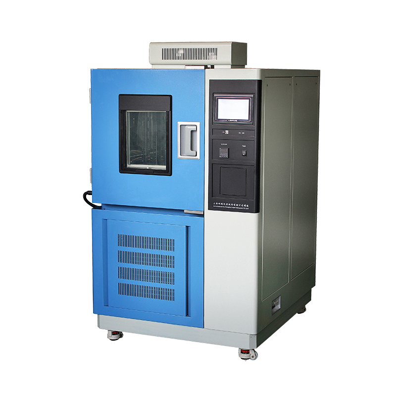
To ensure the electrical, mechanical and thermodynamic integrity of constant temperature and humidity test chambers (hereafter “the chamber”), to standardize operating procedures, and to reduce failure and accident rates, this instruction is established. It applies to all programmable, single-point and walk-in chambers that are newly purchased, in service or relocated.

2. Scope
2.1 Temperature range: –70 °C to +180 °C
2.2 Humidity range: 20 %RH to 98 %RH
2.3 Maximum load: 80 % of name-plate rating
2.4 Applications: reliability testing for electronics, automotive parts, aerospace materials, biomedical products, food and chemicals, etc.
3. Normative References
GB/T 2423.1-2008 Environmental testing for electric and electronic products – Part 2: Test methods – Tests A: Cold
GB/T 2423.2-2008 Dry heat
GB/T 2423.3-2016 Damp heat, steady state
GB/T 5170.2-2016 Inspection methods for environmental testing equipment – Combined temperature/humidity tests
GB 4793.1-2007 Safety requirements for electrical equipment for measurement, control and laboratory use – Part 1: General requirements
ISO/IEC 17025:2017 General requirements for the competence of testing and calibration laboratories
4. Personnel Qualification
4.1 Operators shall hold a “Laboratory Equipment Operation Certificate” and pass annual safety retraining.
4.2 The equipment owner shall possess a low-voltage electrician licence or equivalent electrical-safety qualification.
4.3 Visiting trainees may enter the test area only when accompanied by certified personnel.
5. Installation & Positioning
5.1 Site selection
a) Floor loading ≥ 500 kg/m²; levelness ≤ 3 mm/m
b) Ambient 15 °C–30 °C, RH ≤ 75 %, no direct sunlight
c) Keep away from vibration, strong electromagnetic fields, flammable, explosive, corrosive or radioactive sources
d) Clearances: ≥ 80 cm on sides/rear, ≥ 100 cm above
5.2 Electrical connection
a) Dedicated circuit breaker with leakage protection; earth resistance ≤ 4 Ω
b) Voltage fluctuation ≤ ±10 %; frequency 50 Hz ± 0.5 Hz
c) No live wiring; use crimp terminals with insulated sleeves
d) External cables shall be routed through high-temperature corrugated conduit, fixed in the right-side cable channel; no wrapping or squeezing
5.3 Handling & standing still
a) Tilt angle ≤ 45 °; never invert or lay flat
b) After positioning, stand still ≥ 24 h to let compressor oil return before power-on
c) Remove transport bolts; inspect evaporator, humidifier and fan impeller for misalignment
6. Pre-start Checklist (Daily)
□ Power, earthing and emergency-stop normal
□ Tank level 1/2–2/3; de-ionised water (conductivity ≤ 5 µS/cm)
□ Wet-bulb wick clean, moist, not calcified
□ No tools or samples left inside
□ Door seal intact; no cracks or detachment
□ Fill in checklist and sign
7. Sample Loading Rules
7.1 Total sample volume ≤ 1/3 of working volume; total mass ≤ 80 % of rated load
7.2 Air gap ≥ 5 cm between samples; do not block air outlets or sensors
7.3 Liquid samples must be sealed; vacuum containers need expansion space
7.4 Biological samples shall use secondary containers compliant with UN 2814
7.5 Heat-dissipating load ≥ 500 W requires written approval and recalculation of heat balance
8. Safety During Operation
8.1 Door opening is prohibited while running. If mid-test sampling is unavoidable:
a) Wear heat-insulating gloves and anti-fog goggles
b) Ensure T ≤ 60 °C and RH ≤ 60 %RH inside
c) Stop the chamber; open door 10 mm gap to equalise pressure, then fully open
d) Keep door open ≤ 30 s; log the event
8.2 Do not touch fan impeller, heater or humidifier electrode while running
8.3 On abnormal noise, odour or smoke, press emergency stop and execute Emergency Response Card
9. Programme Setting & Validation
9.1 Dual-person verification: one enters, one checks
9.2 Temperature rate ≤ 1 °C/min (unless specified); humidity rate ≤ 5 %RH/min to prevent condensation
9.3 First run of any new profile requires empty-chamber validation; record 9-point T/RH deviation (corners + centre). Load samples only after pass
9.4 All test curves and alarm logs are stored electronically ≥ 10 years for audit trail
10. Maintenance & Intermediate Checks
10.1 Routine
a) Daily: wipe inner walls; drain residual water
b) Weekly: clean condenser fins (compressed air ≤ 0.3 MPa)
c) Monthly: calibrate T/RH sensors against reference (±0.3 °C / ±2 %RH)
d) Quarterly: test leakage-breaker trip time (≤ 30 ms)
10.2 Annual overhaul
a) Replace compressor oil, dryer filter, wet-bulb wick
b) Verify safety valve, over-temperature protector, low-water protector
c) Obtain third-party calibration certificate (CNAS accredited)
10.3 Common alarms & actions
ERR01 Phase-sequence fault – check phase relay
ERR02 Over-temp – check SSR and fan
ERR03 Humidifier fault – check water level / scale on heater
ERR04 High refrigeration pressure – clean condenser / check ambient
11. Emergency Response
11.1 Electric shock: switch off mains, perform CPR, call 120
11.2 Burn: flush with running water ≥ 15 min, apply sterile dressing, send to hospital
11.3 Refrigerant leak: start exhaust ventilation, evacuate personnel, wear positive-pressure respirator, contact certified recovery company
11.4 Fire: use CO₂ extinguisher, never water; activate fire alarm and follow lab evacuation plan
12. Documentation & Traceability
12.1 Raw records shall contain: equipment ID, programme name, sample ID, start/end time, set/actual T & RH, door openings, anomalies, operator/reviewer signatures
12.2 All records are kept in an unalterable electronic system (LIMS) complying with FDA 21 CFR Part 11
12.3 Records retained ≥ 5 years after equipment retirement to ensure full life-cycle traceability
13. Training & Assessment
13.1 New staff shall complete ≥ 4 h theory training within one week, covering this instruction, electrical safety and chemical compatibility
13.2 Practical exam: empty-chamber ramp 30 °C → 85 °C, 85 %RH, three-point calibration after stabilisation. Pass if deviations within limits and no alarms
13.3 Annual refresher: review ≥ 2 failure cases, conduct ≥ 1 emergency drill; pass mark ≥ 90 %
14. Supplementary Provisions
14.1 This instruction is interpreted by the Laboratory Equipment Management Department and reviewed annually
14.2 Revised promptly when standards are updated, equipment is upgraded, or incidents occur; retraining follows
14.3 Effective upon approval; supersedes “Operating Procedure for Constant Temperature & Humidity Chambers” (Doc No. QP-23-2018)