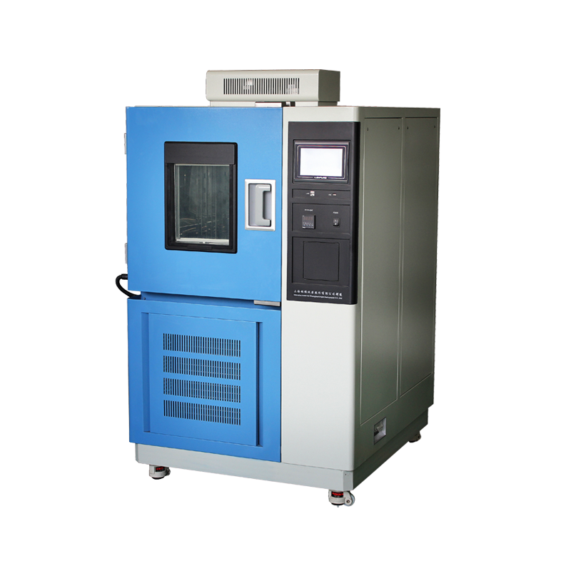
As a core piece of equipment in the field of environmental reliability testing, high and low temperature alternating test chambers play an irreplaceable role in the quality verification processes for electronic components, aerospace materials, automotive parts, chemical products, and other industries. However, during practical application, some operators often neglect several critical operational details due to insufficient understanding of the equipment’s operational mechanisms or inadequate safety awareness. These seemingly trivial aspects actually pose potential risks to the accuracy of test data, operational stability of the equipment, and personnel safety. To ensure efficient testing processes, precise test results, and a safe working environment, the following systematic elaboration on standardized operating procedures and risk prevention and control points for high and low temperature alternating test chambers is hereby presented, aiming to provide technical support for laboratory standardization management.
1. Electrical Safety Protection and Reliability Management of Grounding Systems
During initial equipment installation and positioning, strict implementation of chassis grounding protection measures is mandatory. This requirement is based on fundamental electrical safety standards, aiming to establish a reliable fault current discharge path to prevent electric shock accidents caused by damaged power cord insulation, internal component leakage, or induced voltage accumulation. The grounding resistance value must be periodically tested using a professional grounding resistance tester to ensure it is no greater than 4 ohms, complying with GB 4793.1 Safety Requirements for Electrical Equipment for Measurement, Control, and Laboratory Use. The grounding conductor should be a yellow-green dual-color copper core cable with a cross-sectional area of no less than 2.5mm², and must be securely connected to the laboratory’s independent grounding network; series grounding or virtual connection is prohibited. Neglecting this requirement may cause the equipment chassis to become energized, posing a fatal threat to operators, while also easily causing control system signal interference and resulting in temperature control deviation.
2. Prohibited Operations for Chamber Door Opening/Closing and Temperature Field Stability Mechanisms
During equipment operation of heating and cooling programs, non-essential opening of the test chamber door is strictly prohibited. Opening the door will directly cause violent convection of cold and hot air between the workspace and external environment, destroying the established uniform temperature field distribution and causing local temperature fluctuations exceeding ±5℃, severely affecting test condition stability. More critically, opening the door under high-temperature conditions may cause hot air surges, leading to facial and hand burns for operators; opening under low-temperature conditions will allow large amounts of moist hot air to intrude, quickly frosting the evaporator surface, blocking air channels, reducing heat exchange efficiency, and even causing compressor liquid slugging damage. If opening the door is indeed necessary for observing sample status, this should be done through the observation window; if opening is mandatory, it should be performed when the test chamber is in the normal temperature range (25±5℃) and in a stopped state, with the opening angle not exceeding 30° and duration controlled within 15 seconds.
3. Start-Stop Interval Control for Refrigeration Systems and Compressor Protection Strategies
When the refrigeration unit has been shut down for a short period of 15 minutes, immediate restart is strictly prohibited. This restriction stems from the pressure balance requirements and lubricating oil return mechanism inside the compressor. At the moment of shutdown, the high-pressure side pressure of the system can still reach over 1.5 MPa, while the low-pressure side is in a vacuum state. Forced starting will cause the motor load torque to exceed the rated value by more than 300%, leading to overheating burnout of windings or breakdown of starting capacitors. Simultaneously, a compressor without sufficient oil return may cause lubrication failure of moving parts, accelerating mechanical wear. The correct operational specification is: after shutdown, wait at least 20-30 minutes for the high-low pressure differential to naturally balance and lubricating oil to fully return to the crankcase before restarting. For equipment equipped with intelligent controllers, the system has a built-in delay protection of 3-5 minutes. Manual operations should avoid frequent switching, with daily start-stop cycles not exceeding 6 times.
4. Principle of Independent Power Configuration for High Heat-Generating Samples
If the total heat-generating power of loaded samples exceeds the heat load limit corresponding to the workspace volume (typically calculated as 50W/L), an external independent power supply must be used; direct use of internal equipment sockets is strictly prohibited. The internal power circuit design only bears conventional signal transmission and low-power drive loads, with its rated current generally not exceeding 5A. Connection of high-current loads will cause internal circuit overload heating, accelerated insulation layer aging, and even short-circuit fires. When configuring independent power supplies, ensure the power supply line capacity matches, recommend using cables with a cross-sectional area of no less than 1.5mm², and install independent leakage protection circuit breakers. Sample power cables and equipment control cables should be routed separately, maintaining a distance of more than 10cm to avoid electromagnetic interference affecting temperature sensor signal accuracy.
5. Restrictions on Chamber Door Opening During High-Low Temperature Transition
When executing test profiles transitioning from high to low temperature, chamber door opening time must be strictly controlled to the minimum. After the high-temperature phase, the workspace temperature may reach over 150℃. Rashly opening the door at this time will not only cause the sample to suffer unexpected thermal shock but also generate severe temperature gradients and dew point changes inside the chamber. Moisture-laden hot air rapidly condenses upon encountering cold, forming large amounts of water droplets on air duct panels, sensor sheaths, and sealing strips; this moisture may freeze and expand during subsequent low-temperature phases, causing structural component deformation, rupture of platinum resistance sensor encapsulation, or seal failure. Standard operation requires: if sample adjustment is needed during the holding platform after the heating phase, wait until temperature drops below 60℃ before opening the door, with opening time not exceeding 10 seconds, while quickly wiping visible condensation with absorbent paper.
6. Periodic Verification Mechanism for Safety Protection Devices
The built-in circuit breaker and over-temperature protector are the final defense lines for safeguarding samples and personnel, requiring a regular inspection mechanism. Circuit breakers should undergo breaking capacity testing monthly, using specialized testers to simulate short-circuit currents, verifying whether they can remain non-tripping within 1 hour at 1.13 times rated current and reliably trip within 1 hour at 1.45 times rated current. Over-temperature protectors (typically bimetallic or electronic temperature switches) must be calibrated quarterly using standard temperature sources, with set-point deviation not exceeding ±2℃. During calibration, the main control circuit should be disconnected, and the protector probe placed together with a standard thermocouple in the temperature field to record its action temperature value. If protection device failure is detected, equipment must be immediately stopped and replaced with original certified spare parts; shielding or short-circuiting protection loops for non-compliant operations is strictly prohibited.
7. Energy Consumption Management and Heat Load Control for Lighting Systems
The built-in lighting device of the test chamber should be turned off promptly after sample loading is completed. Although lighting fixtures have relatively low power (typically 15-25W), their cumulative heat generation effect cannot be ignored. Under -40℃ low-temperature conditions, the radiant heat from a single fixture can raise local area temperature by 2-3℃, compromising temperature uniformity indicators. Meanwhile, prolonged operation of lighting accelerates lamp lumen depreciation, shortens service life, and increases unnecessary energy consumption. Modern equipment mostly adopts LED cold light sources, but it remains recommended to keep them off when not necessary. An intelligent mode can be set through the controller: “turn on when door opens, automatically turn off after 30 seconds when door closes,” achieving a balance between energy saving and convenience.
8. Dehumidification Pre-treatment Procedure Before Low-Temperature Testing
Before implementing sub-freezing temperature testing, thorough drying treatment of the workspace interior is mandatory. Residual moisture will solidify into ice crystals under low-temperature environments, potentially blocking air circulation channels, freezing and swelling sample rack fixing structures. More seriously, when moisture penetrates temperature sensor sheaths or equipment gaps, the mechanical stress from freezing expansion can reach over 200 MPa, sufficient to destroy the ceramic framework of PT100 platinum resistance sensors or cause seal ring cracking. The standard dehumidification procedure is: at room temperature, open the chamber door for ventilation for 30 minutes, use clean non-woven fabric to wipe the inner walls, air deflectors, and sample racks; then start the equipment and operate at 80℃ for 1 hour for baking dehumidification, only transferring to the low-temperature program after humidity drops below 10%RH. For extremely low-temperature tests (below -70℃), it is recommended to additionally place silica gel desiccant and install a vacuum drying interface.
9. Heat Balance Waiting Requirements After Test Completion
After the test program terminates, immediate opening of the workspace door is strictly prohibited. The internal temperature may still be in an extreme state (high temperature reaching 180℃ or low temperature reaching -70℃). Immediate door opening will cause violent air convection and heat exchange. Under high-temperature conditions, the outflowing air stream temperature can exceed 100℃, far beyond human tolerance limits, causing second-degree burns within 2 seconds of contact; under low-temperature conditions, instantaneous vaporization of cold air may cause rapid dew point drop in the local micro-environment, frosting the sample surface and affecting subsequent measurement accuracy. The correct practice is: wait for the equipment to naturally return to below 60℃ (after high-temperature tests) or above -10℃ (after low-temperature tests), or execute a “return to normal temperature” program through the controller. Only when the temperature approaches ambient temperature and the pressure balance indicator lights up can the chamber door be opened. This process typically requires 30-60 minutes, depending on the set temperature extreme and workspace volume.
10. Personal Protection Standards for High-Temperature Sample Removal
When retrieving samples from equipment that has just completed high-temperature testing, thermal protective gloves conforming to GB 24541 Hand Protection – Protective Gloves Against Chemicals and Micro-Organisms must be worn. Sample surface temperatures may remain consistent with set values; for example, a sample at 150℃ can still maintain over 120℃ for 5 minutes, and direct contact will cause severe burns. It is recommended to use aramid fiber or asbestos-coated thermal insulation gloves with a Contact Heat Protection Performance Index (HTI) greater than 24, ensuring at least 15 seconds of protection when contacting objects at 300℃. Sample retrieval actions should be swift and accurate, assisted by specialized high-temperature-resistant fixtures. After removal, samples should be immediately placed on ceramic fiber insulation pads with warning signs set up. It is advisable to equip the retrieval area with emergency shower facilities and develop burn emergency response plans to ensure immediate handling when incidents occur.
11. Influence Mechanism of Sample Loading Layout on Temperature Field Uniformity
Test sample placement should follow the principle of uniform distribution, occupying 1/3 to 2/3 of the workspace effective volume, while ensuring unobstructed air circulation channels. Overly dense stacking will obstruct airflow organization, reducing local wind speed to below 0.5m/s, causing temperature change rates to decrease by over 40% and generating temperature gradients exceeding ±5℃, failing to meet the uniformity requirements specified in GB/T 2423.1 standard. Samples should maintain at least 5cm spacing between them, and no less than 10cm distance from inner walls; the areas of air outlet and return openings must not be blocked. For irregular-shaped samples, use hollowed sample racks and adjust placement angles to avoid forming eddy dead zones. The total load mass is recommended not to exceed 80% of the equipment’s nominal capacity to prevent overload wear of transmission components.
12. Risks of Live Operation of Communication Interfaces and ESD Protection Procedures
When connecting equipment to computers for program setting or data acquisition, physical interface connection must be completed in a powered-off state. Live insertion/removal of DB9 serial ports or RJ45 network ports may generate induced voltage of dozens of volts, breaking down the CMOS circuits of controller communication chips, causing communication interruption, data loss, or even motherboard damage. Interface circuits generally lack hot-swap protection design, and electrostatic discharge (ESD) constitutes the primary threat. The standard procedure is: first turn off the main equipment power and wait 5 minutes for capacitor discharge, then turn off the computer power, followed by cable connection, and finally power on sequentially. Anti-static wrist straps should be worn during connection, with interface screws tightened to avoid signal fluctuations caused by poor contact. It is recommended to use opto-isolated communication modules to electrically isolate the communication loop from the main control loop, enhancing anti-interference capability.
13. Energy Management and Electrical Safety Protection During Equipment Idle Periods
After test tasks are completed, the equipment’s main power switch should be completely turned off, not just the stop button on the operation panel. Equipment standby status still consumes 30-50W power, with control systems and sensors remaining energized, wasting energy and increasing lightning surge damage risk. Cutting off the main power can prevent damage to precision components from abnormal nighttime power grid voltage fluctuations and reduce electrical fire probability. The shutdown procedure should be: first execute normal shutdown process through the controller, wait for the compressor and fan to completely stop operating, then disconnect the main power circuit breaker, and finally turn off the laboratory distribution box branch switch. For long-term deactivation (exceeding 7 days), it is recommended to unplug the power cord and place desiccant packs inside the control cabinet to prevent moisture侵蚀 circuit boards. Before reactivation, insulation resistance testing must be performed to ensure it is not less than 2MΩ.
Comprehensive Management System Construction and Continuous Improvement Mechanisms
In summary, the safe and precise use of high and low temperature alternating test chambers is a systematic engineering project involving multiple dimensions including electrical safety, thermal control, mechanical protection, and personnel behavior norms. Laboratory managers should incorporate the aforementioned points into Standard Operating Procedures (SOP), organize quarterly refresher training for operators, and strengthen execution supervision through video monitoring and data auditing. Only by internalizing normative awareness and externalizing it in actions can the equipment’s performance potential be fully realized, ensuring high-quality test data output, while constructing solid safety protection barriers for personnel and equipment, achieving long-term stable and efficient laboratory operations. For abnormal situations not covered in the procedures, a rapid response channel should be established to promptly contact the equipment manufacturer’s technical support team, avoiding problem escalation caused by blind handling.
25.03


Copyright © 2025 Shanghai Linpin Instrument Co., Ltd Copyright
| ICP Number:Shanghai ICP Record No. 12029585-7
| Sitemap


 EN
EN
 中文
中文 Pусский
 Tiếng Việt
 ภาษาไทย
 پاکستانی زبان