A thermal-shock chamber (TSC) is not an off-the-shelf climatic box. Its only purpose is to generate controlled temperature gradients and rapid transfer rates that reveal thermo-mechanical defects. A poor choice will distort test data, delay R&D, fail certification audits, or even trigger a product recall. This paper translates field experience into an engineering checklist for R&D, Quality and ESS engineers.
Operating Principle & Topology
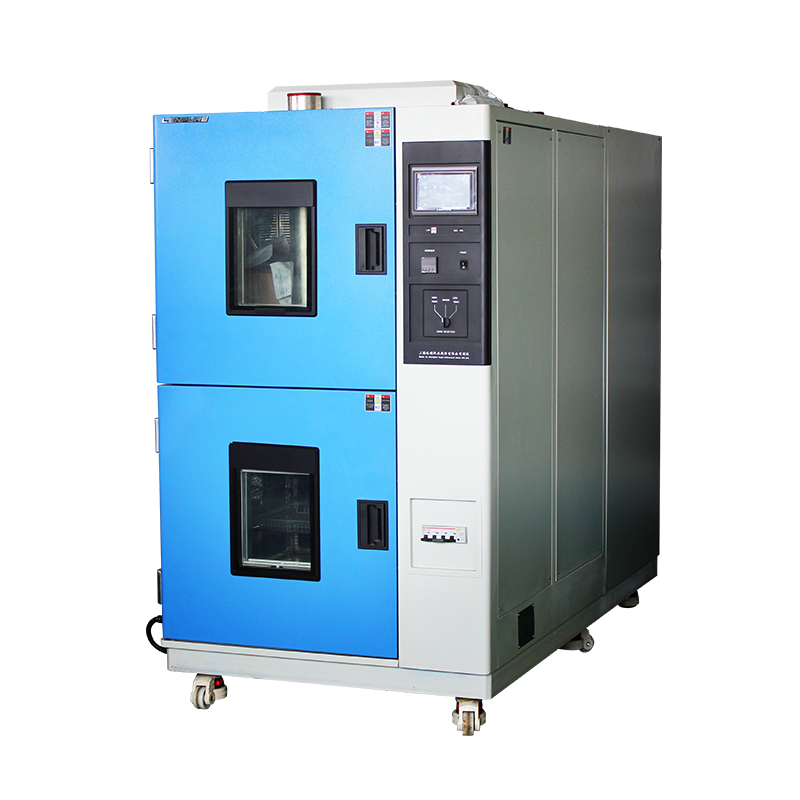
2.1 Two-zone (Basket) Design
Permanent hot and cold cavities; specimen shuttled in a wire-mesh basket within ≤10 s.
Pros: fastest transfer, simplest mechanics, lowest CAPEX.
Cons: high mechanical shock, no powered specimen.
2.2 Three-zone Design
Independent hot, cold and test zones; air-valve switching moves air, not parts.
Pros: powered loading possible, lower mechanical stress, good for large or delicate samples.
Cons: 30–120 s transfer, 25–40 % price premium.
2.3 Thermal Rate Benchmark
Under identical heat-loads two-zone ≥30 °C/min, three-zone 15–20 °C/min.
If the test specification does not mandate transfer mode, decide by required rate and loading capability.
Five-Step Requirements Capture
Step 1 – Identify the Governing Standard
MIL-STD-810H, IEC 60068-2-14, GB/T 2423.22 and JESD22-A104 specify different extremes, dwells, transfer times and cycle counts. Lock the standard before short-listing hardware.
Step 2 – Define Temperature Range & Tolerance
Example: electronics qualified −55 °C…+150 °C.
Add 10 °C margin at each end to cover wall radiation and sensor lag → chamber spec −65 °C…+160 °C.
Step 3 – Quantify Load Characteristics
a) Material & mass (Al, PCB, plastic) – needed for energy balance.
b) Powered or not – 24 VDC/5 A versus 230 VAC/20 A drives cabinet wiring, explosion-proof fans, feed-through design.
c) Self-heating ≥500 W requires active compensation to prevent overshoot.
Step 4 – Fix Working Volume
Sample + fixture + 50 mm air gap on each side.
Common volumes: 50 L, 100 L, 200 L, 500 L.
Each step up adds ≈0.6 m² floor space and 4–6 kW to installed power.
Step 5 – Agree Time Parameters
Default dwell 30 min. If the process needs 10 min or 2 h, state it up-front; refrigeration capacity, heater kW and PID segments must be re-sized.
Key Performance Indicator Table
| KPI | Two-zone Target | Three-zone Target | Notes |
|—–|—————–|——————-|——-|
| Range | −70 °C…+200 °C | −65 °C…+180 °C | LN₂ boost to −80 °C |
| Deviation | ≤ ±2 °C | ≤ ±1.5 °C | 9-point measurement |
| Transfer | ≤ 10 s | ≤ 60 s | No load |
| Rate | ≥ 20 °C/min | ≥ 15 °C/min | Average over range |
| Recovery | ≤ 5 min | ≤ 8 min | 5 kg Al load |
| Noise | ≤ 75 dB(A) | ≤ 72 dB(A) | 1 m in front |
Vendor Evaluation Scorecard
5.1 Certifications
ISO 9001, ISO 14001, CE, UL, CNAS calibration certificates.
5.2 Critical Components
Compressor (Bitzer, Tecumseh), Controller (Eurotherm, Siemens), Solenoid (Danfoss), Sensor (Heraeus).
5.3 Traceability
≥3 reference customers in the same industry within three years; deliver acceptance reports, calibration sheets and contact persons.
5.4 After-sales
Fault response ≤4 h, on-site ≤48 h, ≥2 preventive visits/year, spare-parts availability ≥10 years.
5.5 Upgradability
Modbus-TCP, Ethernet/IP, OPC-UA, MES ready; LN₂ or CO₂ boost ports pre-installed.
Life-Cycle Cost Model (10-year, 100 L three-zone)
| Item | Amount |
|——|——–|
| Energy 180 kWh/d × 300 d × 0.8 ¥ | 4.3 k€ |
| Maintenance 0.8 k€/yr × 10 | 8.0 k€ |
| Downtime 2 × 2 d × 1 k€ | 4.0 k€ |
| Total OPEX ≈ | 16 k€ |
| CAPEX | 28 k€ |
| LCC | 44 k€ |
A 15 % energy saving pays back a 6 k€ price premium within the first three years.
Contract Technical Annex (extracts)
7.1 Acceptance: GB/T 5170.2 method A, no-load & full-load, 100 % data points within spec.
7.2 Metrology: sensors with CNAS calibration, uncertainty ≤0.1 °C, k=2.
7.3 Penalty: 1 % of contract value per 1 °C deviation, cap 10 %; delivery delay 0.5 % per day.
7.4 IP: lifetime free firmware updates, build environment provided to prevent vendor lock-in.
Common Pitfalls & Corrections
Pitfall 1 – Chasing ultimate low temperature
−80 °C needs cascade or LN₂, +40 % energy; over-spec if −55 °C is enough.
Pitfall 2 – Cable-port left open
Ambient moisture migrates, ice builds up, premature evaporator failure.
Pitfall 3 – Volume-based sizing
Sample 300 mm + fixture 100 mm = 400 mm; 100 L height 600 mm suffices—200 L only slows ramps and inflates cost.
Pitfall 4 – Floor loading ignored
500 L unit 800 kg on 0.9 m² → 890 kg/m² may exceed lab floor (500 kg/m²); steel platform or pit required.
Closing
Buying a TSC is not a purchase—it is a requirements project. Translate standards into measurable specs, quantify load and margin, score vendors against KPIs, and lock every technical detail into a traceable contract. Do it once, do it right, and the chamber will deliver data value for ten years instead of trouble tickets.

Copyright © 2025 Shanghai Linpin Instrument Co., Ltd Copyright
| ICP Number:Shanghai ICP Record No. 12029585-7
| Sitemap


 EN
EN
 中文
中文 Pусский
 Tiếng Việt
 ภาษาไทย
 پاکستانی زبان