
Introduction
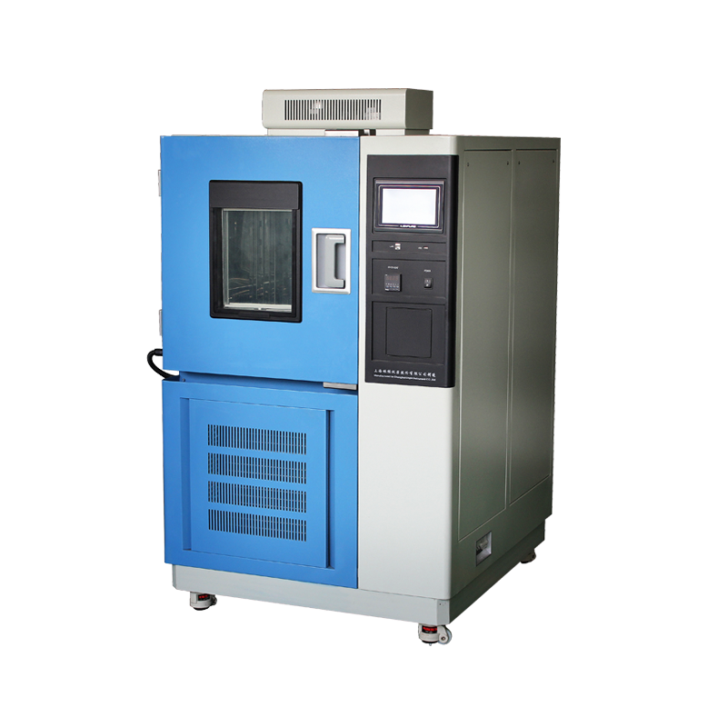
The high-low temperature test chamber is a cornerstone of environmental-reliability verification. Its mission is to reproduce extreme temperature and humidity conditions in a controlled manner so that performance degradation and failure modes of the Device Under Test (DUT) can be assessed across its life cycle. Because capital expenditure is high and technical parameters are complex, any selection error can distort test results, delay programs or trigger repeat purchases. This paper adopts an engineering risk-management perspective to systematically consolidate the selection criteria and to provide actionable guidance for R&D, quality and procurement departments.
Clarifying Requirements: From Test Specification to Quantified Metrics

2.1 Mapping Test Standards
• Military: MIL-STD-810, GJB 150
• Automotive electronics: IEC 60068-2-1/-2/-78, ISO 16750
• Consumer electronics: GB/T 2423, JESD22-A104
Convert each clause of the applicable standard into quantified metrics—temperature range, rate of change, dwell time, humidity tolerance—then back-calculate the required equipment specification.
2.2 DUT Characteristics
• Thermal mass: High-power PSUs demand greater refrigeration capacity.
• Physical volume: PCB cards vs. traction battery packs create vastly different workspace requirements.
• Internal heat dissipation: If ≥ 500 W, dynamic thermal compensation or liquid-cooled auxiliary loops may be needed.
2.3 Usage Scenarios
• Laboratory type: prioritizes accuracy; single-phase 220 V acceptable.
• Production sampling: demands 380 V three-phase, rapid temperature change, 24×7 duty cycle.
• Mobile field testing: requires shock resistance, wide-range voltage input and remote monitoring.
Decomposition & Weighting of Technical Parameters
3.1 Temperature / Humidity Range
Maintain a 15 % margin. If the specification calls for –40 °C to +85 °C, the chamber should nominally reach –55 °C to +100 °C.
3.2 Temperature Rate of Change
A linear 5 °C/min is a common inflection point. If the test plan mandates 15 °C/min, verify compressor power, air-flow path and cold-side PID strategy.
3.3 Uniformity & Fluctuation
• Uniformity: ≤ 2 °C (nine-point empty-chamber method)
• Fluctuation: ≤ ±0.3 °C (per IEC 60068-3-5)
These two metrics define the test error band and must be documented in the technical agreement together with the measurement-point layout.
3.4 Workspace Volume & Load Capacity
Empirical rule:
Effective volume ≥ DUT volume × 3, plus 150 mm air-duct clearance.
For irregular samples (e.g., fully assembled UAVs), perform a 3-D CAD interference check to avoid the pitfall of “fits but cannot be tested accurately”.
3.5 Sealing & Insulation
• Door seal: dual silicone hollow magnetic strips + stainless-steel over-center latches, clamping force ≥ 60 N.
• Enclosure: ≥ 120 mm polyurethane foam, thermal bridge coefficient ≤ 0.25 W/(m·K).
• Leak rate: ≤ 1×10⁻⁶ Pa·m³/s (helium mass-spectrometer leak test).
Seal failure leads to frost build-up, sensor drift and compressor slugging.
3.6 Safety & Compliance
• Over-temperature, over-pressure, earth-leakage, compressor time-delay, DUT power interlock protection.
• CE, UL, CSA approvals and CNAS-traceable calibration certificates.
Structural & Process Evaluation
4.1 Air-Duct Design
Horizontal supply with top return suits flat specimens; vertical supply with side return suits tall specimens. Prevent direct impingement to avoid local over-cooling.
4.2 Refrigeration System
Single-stage cascade (–40 °C), dual-stage cascade (–70 °C), liquid-nitrogen assist (below –100 °C).
Pay attention to COP (coefficient of performance) and noise: scroll compressors < 72 dB(A), screw compressors < 80 dB(A).
4.3 Heating & Humidification
Ni-Cr sheathed heating elements. Humidification via boiler steam or shallow water tray. Boiler systems respond quickly but need de-ionized water; trays are low-maintenance but have high thermal inertia.
4.4 Control System
• PLC with PID algorithm, 20-step programmability.
• Touch screen ≥ 10.4 in, USB/Ethernet data export.
• Remote monitoring: Modbus-TCP, OPC-UA, SNMP.
4.5 Materials & Maintainability
Inner chamber: 304 stainless steel mirror finish Ra ≤ 0.8 µm; outer shell: powder-coated cold-rolled steel.
Removable impeller, pull-out humidifier bucket, magnetic filter screen—maintenance time < 30 min.
Commercial & After-Sales Dimensions
5.1 Supplier Evaluation
• Technical capability: possession of thermodynamic simulation and CFD duct-verification reports.
• Production capacity: monthly output, brand & inventory of core components (compressor, controller).
• Industry references: ≥ 20 customers in the same product category.
• Service network: 7×24 h hotline, in-province 4 h on-site response, spare-parts inventory fill rate ≥ 90 %.
5.2 Life-Cycle Cost (LCC)
Initial purchase ≈ 40 %;
Energy & maintenance ≈ 45 % (compressor, humidifier consumables, calibration);
Downtime loss ≈ 15 % (calculated via hourly production value).
Variable-speed compressors, LED lighting and low-conductivity door seals typically pay back their premium within three years.
5.3 Contractual Terms
• FAT (Factory Acceptance Test): both empty- and full-load profiles, NABL-traceable report.
• SAT (Site Acceptance Test): repeat critical FAT items plus 8 h continuous run.
• Warranty: ≥ 24 months for complete machine, ≥ 36 months for compressor.
• Training: three-level curriculum—operation, calibration, troubleshooting—plus SOP and maintenance manual.
Illustrative Selection Workflow
Step 1: Form a cross-functional team (R&D, Quality, Equipment, Procurement).
Step 2: Translate the test protocol into a “Requirement Specification Table” (28 parameters).
Step 3: Issue an RFI (Request for Information) to ≥ 5 qualified vendors.
Step 4: Technical clarification meeting + on-site audit (focus on enthalpy laboratory and door-seal production line).
Step 5: Weighted scoring (Technical 40 %, Commercial 30 %, Service 20 %, Lead-time 10 %).
Step 6: Execute technical agreement + commercial contract, append FAT/SAT checklist with penalties.
Conclusion
Selecting a high-low temperature test chamber is not a simple comparison of data-sheet numbers, but a systematic trade-off among test standards, DUT characteristics, operating environment, maintenance capability and commercial terms. By establishing a quantified requirement matrix, implementing a life-cycle cost model and introducing third-party validation mechanisms, decision risk can be markedly reduced, ensuring the accuracy and traceability of reliability-test data. Only in this way can the expensive capital investment be transformed into a solid cornerstone of product competitiveness.