Introduction
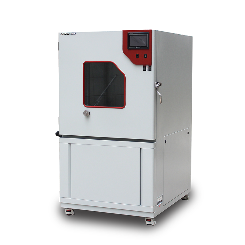
Dust/sand test chambers are environmental simulation devices designed and manufactured in accordance with GB/T 2423.37, IEC 60068-2-68, ISO 20653 and other international standards. They are used to evaluate the sealing reliability and corrosion resistance of locks, automotive/motorcycle parts, seals, power meters and other products under sandstorm conditions. After the 2021 new-generation models were delivered in volume, laboratory utilization has risen sharply, making rapid troubleshooting and reduced downtime a top priority for users. From an engineering perspective, this guide systematically reviews the diagnostic logic for three high-frequency faults—no power, no dust blowing, and no vibration—and provides a preventive-maintenance checklist. Equipment-selection considerations and technical-service offerings are also discussed for laboratory managers, maintenance engineers and purchasing decision makers.
High-Frequency Fault Diagnosis Workflow
2.1 Fault Categories and Impact
Based on after-sales data from the past three years, 78 % of all service calls fall into three categories:
A. Complete loss of power (34 %)
B. No dust blowing (29 %)
C. No vibration (15 %)
The remaining 22 % involve temperature/humidity anomalies, program lock-ups, sensor drift, etc., and usually require remote or on-site support from the manufacturer.
2.2 Loss-of-Power Diagnosis
2.2.1 External Power Verification
• Check whether the plant has a scheduled outage or a tripped breaker.
• Measure the feeder output with a multimeter: line-to-line voltage should be 380 V ±10 % and neutral-to-ground < 5 V. • If a UPS is installed, confirm that it is not in static-bypass mode. 2.2.2 Internal Power Path Inspection • Visually inspect the main terminal block for loose or burnt wiring. • Verify equal potential across the main breaker’s upper and lower terminals. • Check control-panel fuses and miniature circuit-breaker indicators; replace fuses or reset breakers with identical ratings when necessary. 2.2.3 Typical Misdiagnosis Case A user reported “no power.” Investigation revealed that the central exhaust system in the constant-climate laboratory had triggered the phase-sequence protector. Resetting the phase sequence restored power immediately. 2.3 No-Dust-Blowing Diagnosis 2.3.1 Blower Operation Status • Listen for blower start-up noise. If absent, use a clamp meter to check three-phase currents for balance. • If current is zero, check the VFD for fault codes such as E.OC or E.OV; reset or replace the module per the manual. 2.3.2 Ductwork & Nozzles • Remove the top service cover and inspect for dust caking in the air duct. • Blow compressed air (0.4 MPa, clean) in reverse; use a soft brush on nozzles if necessary. • Verify dust dryness: moisture > 2 % causes caking. Run a 30 min pre-heat cycle before testing.
2.3.3 Dust-Feed System
• Ensure the vibratory feeder amplitude dial is at 30 %–50 %.
• Confirm dust level is at least 50 mm above the lower-level sensor.
• In recirculating systems, check the cyclone discharge valve for jamming.
2.4 No-Vibration Diagnosis
2.4.1 Vibration Motor
• With power off, manually rotate the motor fan to detect mechanical seizure.
• Measure insulation resistance; cold-state value should be ≥ 5 MΩ.
• Inspect star/delta links in the terminal box for looseness.
2.4.2 Control Circuit
• Verify that PLC output Q0.3 (example) delivers 24 V DC during the vibration cycle.
• Observe solid-state-relay (SSR) indicator; if lit but motor is off, the SSR is likely failed.
• If a VFD is used, check parameter P3-09 (vibration frequency) has not been set to zero.
2.5 General Troubleshooting Rules
Follow the sequence “external before internal, power before control, mechanical before electrical, simple before complex,” and always lock-out/tag-out. All work must be performed by personnel holding a low-voltage electrician certificate.
Preventive-Maintenance System
3.1 Environmental Conditions
• Temperature: 15 °C – 25 °C
• Relative humidity: ≤ 85 % RH, non-condensing
• Ventilation: ≥ 0.8 m clearance on all sides
• Lighting: avoid direct sunlight; use blinds if necessary
• Hazards: keep away from flammable, explosive or corrosive substances
3.2 Periodic Maintenance Checklist
Daily
• Wipe external dust from the chamber.
• Verify that the emergency-stop button is reset.
Weekly
• Vacuum residual dust inside the chamber.
• Inspect blower filter; replace immediately if damaged.
Monthly
• Calibrate dust-concentration sensor against a reference dust disc.
• Check vibration-motor mounting bolts (torque to 25 N·m).
Quarterly
• Inspect terminal temperature rise in the electrical cabinet (IR camera ≤ 55 K).
• Clean cooling-fan filters in the control box.
• Back up PLC program and HMI recipes.
Annually
• Commission a third-party CNAS-accredited lab to calibrate temperature, air velocity and dust concentration.
• Replace blower bearing grease (Shell Gadus S2 V220, 0.1 kg).
3.3 Spare-Parts Strategy
Recommended on-site stock: 1 main breaker, 5 fuses, 1 dust-concentration sensor, 2 SSRs, 1 blower bearing set, 1 vibration motor. Continuous-production users may sign a vendor-managed-inventory (VMI) agreement to reduce downtime.
Equipment Selection & Technical Upgrades
4.1 2021 Model Highlights
• Modular enclosure: 304 stainless-steel liner, 1.2 mm powder-coated cold-rolled steel exterior, 50 mm fire-retardant PU insulation.
• Energy-saving blower: EC backward-curved centrifugal fan, 25 % less energy than AC fans.
• Adaptive dust recovery: cyclone + pulse-jet two-stage filtration, recovery ≥ 95 %.
• Smart monitoring: Ethernet standard, MQTT & Modbus TCP support for remote data access and alarms.
4.2 Customization Capability
Non-standard volumes (500 L – 3000 L), special dusts (Arizona A2, Portland Cement), extreme temperatures (–20 °C – +80 °C) and MIL-STD-810H compliance are available. Turnaround: design, CFD simulation, engineering review and prototype within three weeks.
4.3 Technical-Service Matrix
• Remote diagnostics: 7×24 h VPN access, average response 30 min.
• On-site support: 30 service centers nationwide, 4 h arrival (core cities in Yangtze River Delta, Pearl River Delta, Beijing–Tianjin–Hebei).
• Training & certification: six end-user training sessions per year, dual certificates for operators and maintainers.
• Metrology & calibration: in cooperation with CNAS L0123 lab, providing traceable certificates.
By implementing a closed-loop management system of “tiered fault diagnosis—preventive maintenance—technical upgrade,” users can extend MTBF beyond 5 000 h, cut spare-parts inventory by 30 % and reduce annual maintenance costs by 20 %. Our company is committed to continuous innovation and full-lifecycle service to help customers achieve zero unplanned downtime. All industries are welcome to visit our factory for technical exchanges and business discussions, and to jointly advance the high-quality development of reliability testing.


Copyright © 2025 Shanghai Linpin Instrument Co., Ltd Copyright
| ICP Number:Shanghai ICP Record No. 12029585-7
| Sitemap


 EN
EN
 中文
中文 Pусский
 Tiếng Việt
 ภาษาไทย
 پاکستانی زبان