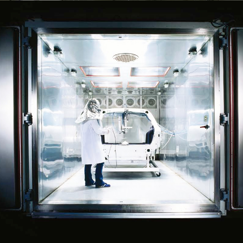
Introduction
The thermal shock chamber (TSC) is a cornerstone instrument in environmental-reliability testing. By exposing a specimen to rapid alternations between extremely high and extremely low temperatures, it reproduces the severe thermal excursions encountered during service or transport. The goal is to verify whether the specimen’s materials, structure and functionality remain within design tolerances under cyclic thermal expansion and contraction. With the rapid development of 5G communications, new-energy vehicles, aerospace and advanced semiconductor packaging, industry now demands TSCs that are faster, more accurate, more energy-efficient and more stable. Three primary temperature-shock concepts have emerged: two-zone gaseous shock, two-zone liquid shock and three-zone static shock. This paper systematically compares these concepts from six perspectives—working principle, structural features, performance indices, application scenarios, maintenance costs and development trends—to provide guidance for equipment selection and process optimisation.
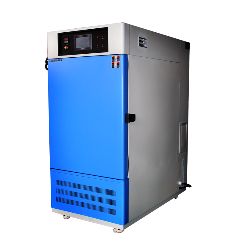
Two-Zone Gaseous Thermal Shock Chamber
2.1 Working Principle
The chamber consists only of a high-temperature (HT) zone and a low-temperature (LT) zone. The specimen is mounted in a carrier basket that is driven vertically between the two zones by a servo motor via a ball screw or synchronous belt. When the basket enters the HT zone, a centrifugal fan blows heated air at high velocity across the specimen; when it descends into the LT zone, an axial fan directs chilled air in the same manner. Because the heat capacity of air is low, the specimen temperature changes rapidly, creating the desired thermal shock.
2.2 Structural Features
(1) Dual-cavity architecture: an insulated door interlocks with basket movement to maintain zone isolation and thermal integrity.
(2) Carrier basket: one-piece aerospace-grade aluminium alloy, light, strong and corrosion-resistant; dynamic seals use dual FKM O-rings for wear and temperature resistance.
(3) Fan systems: HT zone employs centrifugal recirculation fans, LT zone axial fans, both inverter-controlled for uniformity and low noise.
(4) Refrigeration: cascade refrigeration for the LT zone; electric heaters with PID control for the HT zone; independent sources prevent cross-interference.
2.3 Performance Indices
• Temperature range: +60 °C to +200 °C (HT), –65 °C to –10 °C (LT)
• Transition time: ≤15 s (basket movement + air stabilisation)
• Recovery time: ≤5 min (IEC 60068-3-5, no load)
• Temperature fluctuation: ≤±0.3 °C
• Spatial uniformity: ≤±2 °C (no load)
2.4 Application Scenarios
Ideal for small, lightweight and mechanically robust components such as electronic devices, PCBAs, opto-electronic connectors. Its rapid transition meets MIL-STD-202, JESD22-A104 and similar standards.
2.5 Maintenance Costs
The basket and drive train are subject to mechanical fatigue. Lubrication, seal and belt replacement are required periodically. Motors, inverters and sensors are also wear parts. Annual maintenance averages 5–8 % of the purchase price.
Two-Zone Liquid Thermal Shock Chamber
3.1 Working Principle
The architecture is similar to the gaseous version, but the cavities are filled with high-stability silicone oil (or fluorinated fluid). The basket shuttles between hot and cold oil baths. Direct liquid contact gives far lower thermal resistance, so the temperature change rate is 30–50 % faster than in air.
3.2 Structural Features
(1) Liquid circulation: magnetically coupled pumps ensure uniform flow in both cavities.
(2) Flexible isolation: stainless-steel bellows compensate for thermal expansion, preventing weld fatigue.
(3) Degassing system: vacuum degasser plus micro-filter prevent bubbles that would impede heat transfer.
(4) Leak protection: double stainless-steel drip trays with leak alarms.
3.3 Performance Indices
• Temperature range: +50 °C to +180 °C (HT), –65 °C to 0 °C (LT)
• Transition time: ≤10 s
• Recovery time: ≤5 min
• Spatial uniformity: ≤±1.5 °C (full oil load)
Because of the high density of the liquid, basket load must be limited to ~20 kg to avoid drive overload.
3.4 Application Scenarios
Suited to power semiconductors, IGBT modules and laser diodes where the maximum temperature ramp is critical. Liquid shock shortens test cycles and increases throughput.
3.5 Maintenance Costs
Oil must be analysed every two years for dielectric strength and acid number; complete replacement may be necessary. Pumps, filters and seals are consumables. Annual maintenance averages 7–10 % of purchase price, and oil spills carry both clean-up cost and environmental risk.
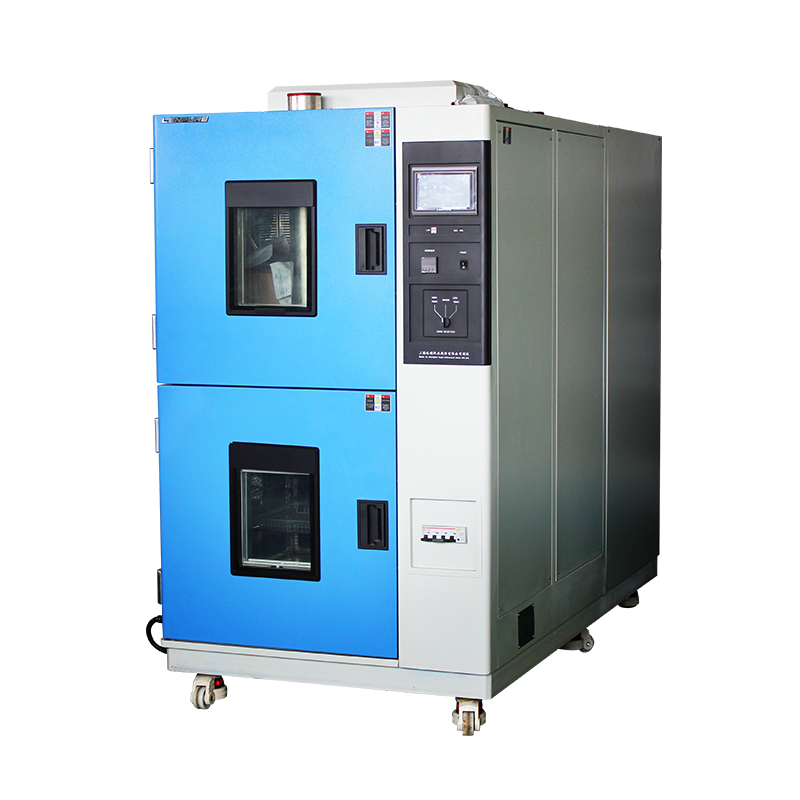
Three-Zone Static Thermal Shock Chamber
4.1 Working Principle
A third zone—the ambient zone (AT)—is added between the HT and LT zones. The specimen remains static in the AT; no mechanical movement is required. Servo-driven dampers instantaneously open to direct hot or cold air into the AT, creating the thermal shock. After the shock, the dampers switch to restore ambient temperature, facilitating specimen loading/unloading. Thus, this is a “static” shock, contrasting sharply with the “dynamic” methods above.
4.2 Structural Features
(1) Tri-zone layout: HT and LT zones flank the AT; airflow is CFD-optimised for uniformity.
(2) Servo dampers: brushless-motor-driven circular dampers with ≤1 s actuation time and ≤0.1° positioning accuracy.
(3) Thermal storage: finned aluminium heat sinks store energy while dampers are closed, improving efficiency.
(4) Smart defrost: hot-gas bypass defrost in the LT zone is triggered by dew-point logic to save energy.
4.3 Performance Indices
• Temperature range: +60 °C to +220 °C (HT), –70 °C to 0 °C (LT)
• Transition time: ≤3 s (damper switch + air stabilisation)
• Recovery time: ≤5 min
• Temperature fluctuation: ≤±0.2 °C
• Spatial uniformity: ≤±1 °C (full load)
Because the specimen remains stationary, heavier (≤50 kg) and larger (≤100 L) items can be tested.
4.4 Application Scenarios
Ideal for large packaged items, battery modules, automotive displays and composite structures. The absence of mechanical vibration is gentle on sensitive devices and conforms to IEC 60068-2-14 Nb and GB/T 2423.22.
4.5 Maintenance Costs
Only the damper mechanism moves, so wear is minimal. Inverter-driven compressors improve efficiency by >15 %. Annual maintenance is ~3–5 % of purchase price, giving the best overall economy.
Comparative Summary
• Temperature ramp: liquid > gaseous ≈ static
• Mechanical complexity: gaseous (basket) > liquid (basket + oil) > static (damper)
• Load capacity: static > gaseous ≈ liquid
• Maintenance cost: gaseous ≈ liquid > static
• Standard compliance: all three meet MIL, IEC, JEDEC and GB specifications, but static excels for large specimens
• Environmental friendliness: gaseous and static have no liquid-leak risk, superior to liquid
Development Trends
• Intelligence: IoT and edge computing enable remote monitoring, predictive maintenance and energy optimisation.
• Energy efficiency: variable-speed heat pumps, CO₂ transcritical cycles and magnetic-bearing compressors further cut power consumption.
• Modularity: HT, LT and AT modules can be flexibly combined for “one-to-many” parallel testing.
• Ultra-low shock: cascade refrigeration plus liquid nitrogen pushes the low limit below –100 °C for deep-space and quantum applications.
• Data integration: seamless connection to MES/LIMS automatically generates ISO 17025-compliant reports and enables full traceability.
Conclusion
Temperature-shock methods have evolved from a single dynamic concept to a diversified portfolio where dynamic and static, gaseous and liquid approaches coexist and complement each other. Two-zone gaseous shock is valued for its simple structure and moderate cost; two-zone liquid shock wins on maximum ramp rate; three-zone static shock, with its stability, reliability and energy efficiency, has become the mainstream choice. As new materials, processes and standards continue to emerge, thermal-shock technology will advance toward broader temperature ranges, faster ramps, higher accuracy and greener operation, safeguarding continuous innovation in global high-end manufacturing.
26.05


Copyright © 2025 Shanghai Linpin Instrument Co., Ltd Copyright
| ICP Number:Shanghai ICP Record No. 12029585-7
| Sitemap


 EN
EN
 中文
中文 Pусский
 Tiếng Việt
 ภาษาไทย
 پاکستانی زبان