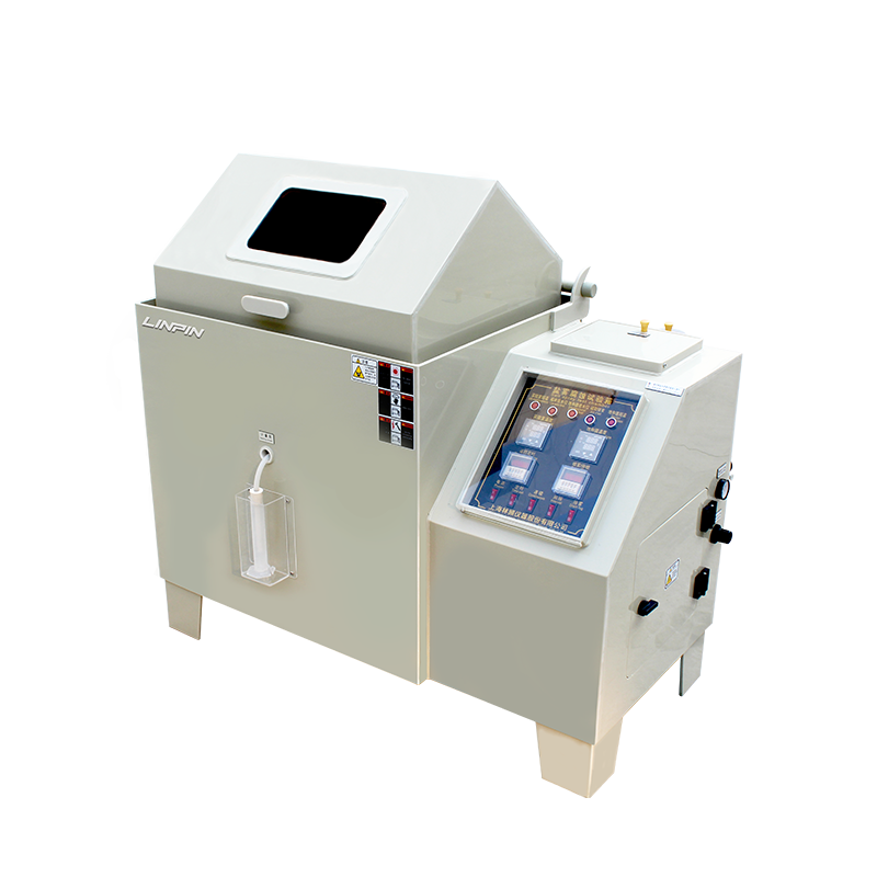
Salt fog (salt spray) test chambers are standardized instruments designed to determine the corrosion resistance of materials and their protective coatings. The test results serve as a technical basis for reliability design, quality control, and service-life prediction in industries such as electrical and electronic engineering, digital components, plastics, aerospace equipment, and many others. By reproducing harsh marine or industrial atmospheres in an accelerated manner, salt fog chambers can replicate long-term corrosion effects within a short time, thereby shortening product development cycles and reducing test costs.
Operating Principle
1.1 Corrosive Medium
The conventional test solution is a 5 % (m/m) sodium chloride solution in de-ionized water. When a more aggressive environment is required, 0.26 g of copper(II) chloride dihydrate (CuCl₂·2H₂O) may be added per litre of solution.
1.2 Atomization Method
Compressed air, after pressure regulation and pre-heating, atomizes the corrosive solution into a salt fog with droplet diameters of 1–5 µm. The fog is uniformly deposited on the specimen surfaces.
1.3 Key Control Parameters
• Salt fog sedimentation rate: 1.0–2.0 mL / 80 cm²·h (funnel method).
• Test zone temperature: 35 °C ± 2 °C.
• pH of collected solution: 6.5–7.2 (measured at 35 °C).
The chamber is equipped with a closed-loop temperature control system and an automatic brine replenishment system to ensure that these parameters remain constant throughout the test period.
Test Preparation
2.1 Power and Air Supply
Connect the main power supply (AC 220 V 50 Hz or AC 380 V 50 Hz, as specified on the nameplate) and the air compressor power; verify reliable grounding. Attach an Φ8 mm air hose to the rear air filter.
2.2 Purified Water Supply
Open the chamber lid and fill the saturator tower and the rear water inlet with Grade-III (or higher) purified water per GB/T 6682 until the “low water level” indicator on the control panel extinguishes.
2.3 Seal Water Trough and Wet-Bulb System
• Fill the door-groove (seal water trough) to the level of the spacer block to prevent salt fog leakage.
• Fill the wet-bulb cup with purified water; immerse one end of a clean wick in the cup and cover the wet-bulb temperature sensor with the other end, ensuring the wick is free of salt contamination.
2.4 Brine Preparation and Loading
Dissolve the salt completely, filter twice, and pour the solution into the transparent brine reservoir (liquid level not above the bottle shoulder). Activate the “Auto Refill” push-button; the system will continuously feed brine to the spray tower by siphon action.
Specimen Installation
3.1 Pre-treatment
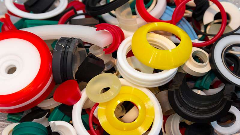
Degrease, clean, and dry specimens per the relevant product standard or technical agreement; record initial surface roughness, coating thickness, and other baseline data.
3.2 Mounting Arrangement
• Expose the test surface upward at an angle of 15°–30° to the vertical.
• Ensure that specimens do not touch one another or obstruct free sedimentation of salt fog.
• Use inert supports (e.g., PVC or PP) to avoid galvanic corrosion.
3.3 Test Duration
Typical cycles are 24 h, 48 h, 96 h, 168 h, or longer, as specified in the product standard or contractual agreement. A blank control specimen must be included in each batch.
Test Monitoring
4.1 Operational Checks
Record temperature, sedimentation rate, and pressure readings every 8 h; stop the test immediately for troubleshooting if any abnormality is detected.
4.2 Brine Replacement
Replace the brine after a cumulative running time of 168 h or when the sedimentation rate falls below 1.0 mL/h.
4.3 Safety Precautions
Do not open the chamber door during the test. If intermediate inspection is required, use the built-in light and observation window. After the test, switch off heating and atomization first; open the door only after the chamber has cooled to room temperature.
Post-Test Treatment and Evaluation
5.1 Cleaning
Rinse the specimen surfaces gently with running purified water (≤0.2 MPa) to remove salt deposits; then dip-rinse for 2 min in purified water below 35 °C to avoid coating softening.
5.2 Recovery
Place specimens in a recovery atmosphere of 23 °C ± 2 °C and 45 %–55 % RH for 2 h; extend to 24 h if thorough drying of the coating is required.
5.3 Result Assessment
Evaluate per ISO 10289, GB/T 6461, or applicable product standards:
• Excellent: No corrosion spots, no blistering, no cracking, and no substrate rusting.
• Acceptable: Defect area below specified limits without affecting functional performance.
• Rejected: Defect area exceeds limits or functional failure occurs.
Supplementary analyses such as metallography, electrochemical impedance spectroscopy (EIS), or adhesion tests may be employed when necessary.
Maintenance and Calibration
6.1 Routine Maintenance
After each test, drain and rinse the saturator tower, test chamber, and brine tank with purified water; dry thoroughly. Inspect nozzle wear, heater scaling, and seal ageing monthly.
6.2 Calibration Interval
Calibrate temperature, sedimentation rate, and pressure sensors every 12 months; all reference instruments must be traceable to national measurement standards.
6.3 Troubleshooting
• Low sedimentation: check for nozzle blockage, low air pressure, or abnormal brine concentration.
• Temperature runaway: inspect solid-state relays, heater elements, and Pt-100 RTDs.
• Chamber leakage: replace door seals or reinstall the glass window gaskets.
Documentation and Reporting
Maintain fully traceable records throughout the test, including but not limited to:
• Test request form, specimen IDs, and pre-test photographs;
• Brine preparation log and environmental monitoring sheets;
• Post-test photographs, ratings, and defect records;
• Calibration certificates and maintenance logs.
The final test report shall be reviewed and authorized by a signatory approved under the laboratory’s quality system and, when applicable, bear CNAS/CMA accreditation marks.
Conclusion
As a critical apparatus for accelerated corrosion simulation, the salt fog test chamber requires rigorous procedural discipline. Strict adherence to the above preparation, monitoring, evaluation, and maintenance protocols ensures scientific, impartial test data, providing a reliable basis for material research, process optimization, and quality assurance.


Copyright © 2025 Shanghai Linpin Instrument Co., Ltd Copyright
| ICP Number:Shanghai ICP Record No. 12029585-7
| Sitemap


 EN
EN
 中文
中文 Pусский
 Tiếng Việt
 ภาษาไทย
 پاکستانی زبان