Introduction
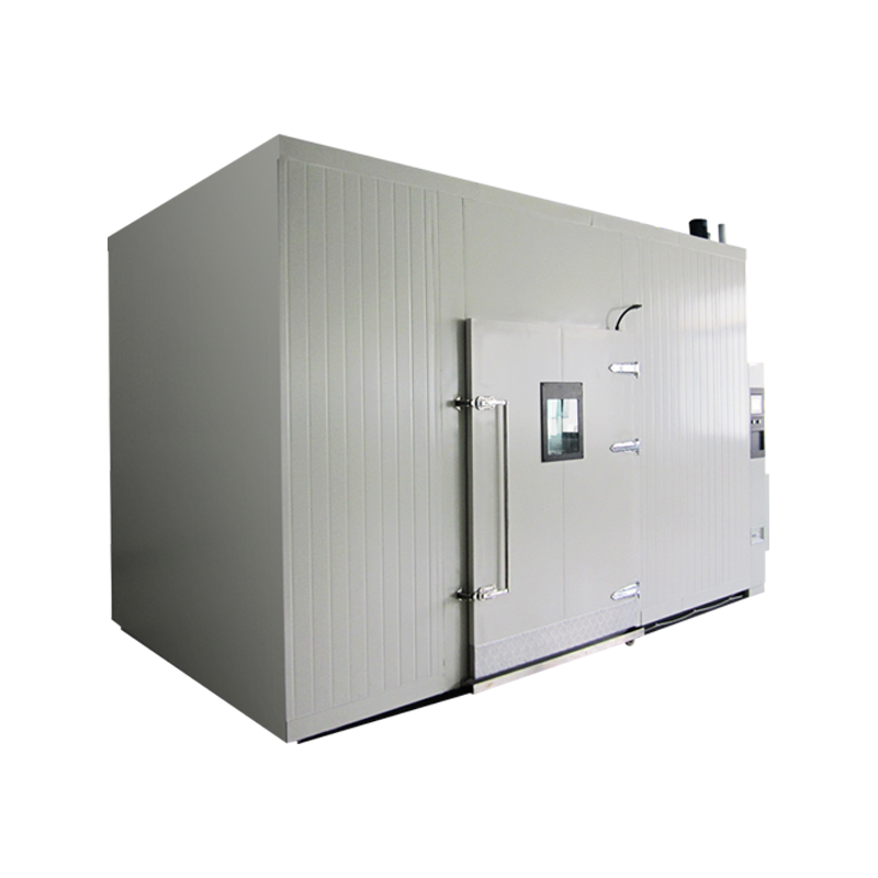
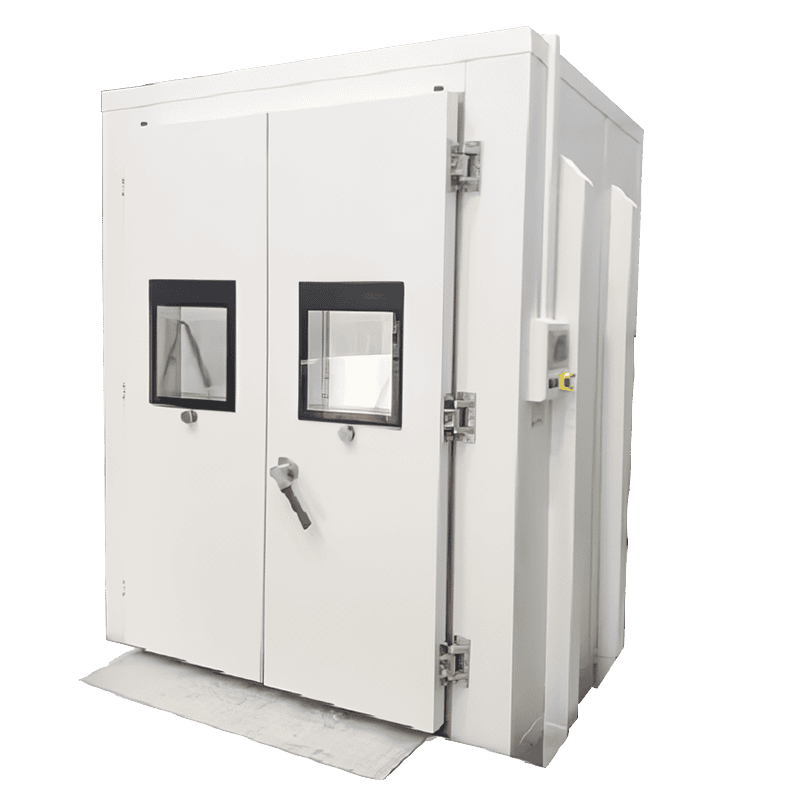
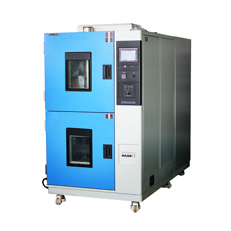
In the field of environmental reliability testing, thermal shock test chambers are widely used to evaluate the adaptability and lifetime degradation of electronic components, materials, and complete products under rapid and extreme temperature transients. Whether the chamber can faithfully reproduce the temperature-profile specified by the standard depends not only on the design margin of the refrigeration/heating system, but also on the cabinet structure, air-duct layout and thermal insulation scheme. All of these hardware links, however, must ultimately be regulated through the closed-loop chain of “sensor–controller–actuator”. As the first element of the information chain, the sensor’s performance directly determines the equipment’s indication error, overshoot amplitude, recovery time and long-term stability. Written in a formal technical style, this paper systematically expounds the operating principles, selection criteria, installation essentials and error-control strategies of sensors commonly used in thermal shock test chambers (thermocouples, platinum resistance thermometers, infrared radiation thermometers, digital bus sensors, etc.). Combined with the latest metrology standards and industrial cases, engineering recommendations for improving test accuracy are proposed for equipment developers, metrologists and test engineers.
Functional Positioning of Sensors in Test Chambers
Original data acquisition unit for temperature values
Sensors convert the invisible temperature field inside the working space into quantifiable and transmittable electrical parameters, forming the source for all subsequent control, recording, alarm and traceability operations.
Feedback reference for control algorithms
PID, fuzzy-PID, Model Predictive Control (MPC) and other algorithms all take the real-time sampled value of the sensor as the feedback variable. If the reference is distorted, even the most advanced algorithm cannot eliminate the systematic error.
Threshold monitor for the safety chain
Failures such as over-temperature, under-temperature, excessive rate of change, or sensor wire-break first manifest themselves as abrupt changes in the sensor signal. The sensor therefore assumes the dual safety duty of protecting both the equipment and the specimen.
Link for metrological traceability
According to ISO/IEC 17025 and GB/T 19022, the chamber must periodically undergo calibration of temperature deviation, fluctuation and uniformity. As the bridge between the unit under test and the standard, the integrity of the sensor’s traceability chain determines the international mutual recognition of the calibration result.
Mainstream Sensor Types and Measurement Principles
3.1 Thermocouple
a. Seebeck effect
Two dissimilar conductors A and B form a closed circuit. When their junctions are kept at different temperatures T₁ and T₂, a thermo-electromotive force E_AB is generated:
E_AB = α(T₁ – T₂) + 0.5β(T₁² – T₂²)
where α and β are material-specific coefficients.
b. Common types and ranges
Type K (–200 °C to +1 250 °C), Type N (–200 °C to +1 300 °C) and Type T (–200 °C to +350 °C) are mainstream choices for thermal-shock chambers. Type K, featuring good oxidation resistance, moderate linearity and low cost, accounts for more than 70 % of applications.
c. Cold-junction compensation
According to the law of intermediate temperatures, any fluctuation in cold-junction temperature produces a systematic offset. Modern acquisition modules commonly adopt a PT1000 cold-junction sensor plus a digital temperature chip, keeping the compensation error within ±0.1 °C.
3.2 Platinum Resistance Thermometer (RTD, Pt100/Pt1000)
Based on the positive temperature coefficient of platinum, IEC 60751 stipulates:
R(t) = R₀(1 + At + Bt² + Ct³)
where R₀ is the resistance at 0 °C and A, B, C are constants. Pt100 offers excellent reproducibility and long-term stability (annual drift ≤ 0.05 °C) in the –70 °C to +200 °C range, making it suitable for the “reference channel” of high-precision chambers.
3.3 Infrared Radiation Thermometer (IRT)
For non-contact, fast-moving specimen surfaces (e.g. semiconductor wafers, relay housings), thermopile detectors in the 8–14 µm band are used, giving a t₉₀ response time ≤ 50 ms and avoiding the thermal-inertia error caused by thermocouple mass loading. Main error sources are emissivity setting, field-of-view contamination and ambient reflection, requiring black-body calibration and algorithmic correction.
3.4 Digital Bus Sensors (I²C, RS-485, CAN)
New-generation sensors integrate ADC, calibration coefficients and linearisation algorithms inside a TO-92 or stainless-steel probe, outputting a digital temperature value directly. This eliminates noise from long-line transmission and thermocouple inhomogeneity, supports TEDS (Transducer Electronic Data Sheet) automatic identification, and facilitates the construction of smart laboratories.
Influence Mechanisms of Sensors on Test Accuracy
4.1 Time constant τ and temperature overshoot
τ = ρcₚV/(hA), where ρ is density, cₚ specific heat, V probe volume, h convection coefficient and A surface area. A larger τ means slower response, causing the controller to “think” the target has not been reached and to continue heating/cooling, thus producing overshoot. Since the transition cycle in a thermal-shock chamber is usually ≤ 5 min, τ ≤ 10 s is required. In practice, exposed-junction Type K wires of φ0.5 mm or thin-film Pt100 are used, and τ is further reduced by decreasing sheath diameter and increasing flow velocity.
4.2 Heat-conduction error
If the probe touches the wall or is mounted on a metal bracket, an additional heat bridge is introduced, making the indicated temperature deviate from the air temperature. Low-conductivity PEEK or PTFE brackets should be used, and the sensing point must be kept ≥ 20 mm from any wall.
4.3 Self-heating error
For RTDs, the excitation current I produces Joule heat Q = I²R. If heat dissipation is poor, the reading will be high. IEC 60751 recommends a self-heating coefficient ≤ 0.2 °C mW⁻¹ for Pt100; a 1 mA constant-current source can meet the ±0.05 °C accuracy requirement.
4.4 Electromagnetic compatibility (EMC)
High-power compressors and solid-state relays generate dv/dt and di/dt during switching, which can couple into the millivolt-level thermocouple signal through inter-wire capacitance and mutual inductance, causing spike interference. Countermeasures include shielded twisted-pair cable, differential amplification, hardware RC plus digital FIR filtering, and floating-ground techniques.
4.5 Uniformity and loading effects
GB/T 2423.22 requires temperature uniformity ≤ 2 °C (–65 °C to +150 °C). Sensors must be placed at nine points: three vertical levels, each with four corners plus the centre. Poor sensor consistency will amplify or mask chamber airflow defects, leading to misjudgement.
Engineering Practice for Sensor Selection and Positioning
Accuracy class
The expanded uncertainty (k = 2) after calibration should be ≤ 1/3 of the test-allowable error. For example, if the specification permits ±2 °C deviation, sensor calibration uncertainty must be ≤ 0.7 °C.
Redundancy strategy
For critical tests (aerospace-grade parts), a “two-out-of-three” voting logic is adopted: three identical thermocouples are installed side-by-side; the controller compares them in real time and shuts down immediately if any one deviates beyond the limit.
Quick-lock structure
M12 stainless-steel aviation connectors plus extension compensating cables facilitate periodic calibration and avoid Seebeck-coefficient drift caused by repeated terminal tightening.
Anti-condensation and pressure-proof
During low-temperature shock, the dew-point difference often exceeds 30 °C. Sensor sheaths must be sealed to IP67, with molecular-sieve desiccant inside the junction box. Liquid-nitrogen-cooled chambers must withstand 0.4 MPa internal pressure, requiring sheath wall thickness ≥ 0.3 mm.
Latest Standards and Metrological Trends
GB/T 5170.10-2021 “Methods for Verification of Environmental Testing Equipment—Thermal Shock Test Chambers” specifies:
a) Calibration points shall cover minimum, maximum and mid-range;
b) Sensor sampling frequency ≥ 1 Hz, recording interval ≤ 30 s;
c) Cold-junction compensation method and uncertainty budget shall be documented.
IEC 60584-1:2021 tightens the reference function for thermocouples; the maximum deviation of Type K in the –200 °C to 0 °C range is reduced from ±2.2 °C to ±1.5 °C, and the updated table became mandatory on 1 Jan 2023.
JJG (Aerospace) ×××-2025 (draft) introduces the concept of “dynamic temperature deviation”: under a rate of 5 °C min⁻¹, the 30 s sliding average deviation shall be ≤ ±1 °C, imposing stricter requirements on sensor response and digital filtering.
Failure Cases and Improvement Measures
Case 1: A third-party laboratory experienced premature specimen failure during –55 °C ↔ +125 °C cycling. Root cause: micro-cracks in the Type K sheath allowed moisture ingress, causing a +1.8 °C drift in thermal EMF. Improvement: replace with 316 L MgO-insulated mineral-insulated cable and perform 10 MPa helium leak testing.
Case 2: During communication-power-module tests, the controller displayed ±6 °C spikes at switching instants. Investigation revealed beat-frequency interference between the compressor inverter carrier and the acquisition card sampling rate. Improvement: add a second-order RC passive filter (f_c = 10 Hz) at the thermocouple input and shift sampling frequency to a non-integer 9.7 Hz, reducing spikes to ±0.3 °C.
Conclusion
Sensors in thermal shock test chambers are far from simple “temperature probes”; they are precision front ends that integrate materials science, thermodynamics, electronic measurement and data science. As third-generation semiconductors, automotive-grade chips, low-orbit satellites and other high-end applications demand temperature-profile fidelity of ≤ ±0.5 °C or even ±0.3 °C, sensor selection, positioning, calibration and maintenance must be embedded in the core of the chamber’s life-cycle quality management. In the future, emerging technologies such as MEMS micro-thermocouple arrays with AI self-calibration, quantum-cascade-laser absorption spectroscopy (QCLAS) for non-contact thermometry, and digital-twin real-time mapping will further propel thermal-shock testing from “empirical replication” to “digital precision”, providing rock-solid metrological support for the reliability verification of high-end equipment.


Copyright © 2025 Shanghai Linpin Instrument Co., Ltd Copyright
| ICP Number:Shanghai ICP Record No. 12029585-7
| Sitemap


 EN
EN
 中文
中文 Pусский
 Tiếng Việt
 ภาษาไทย
 پاکستانی زبان