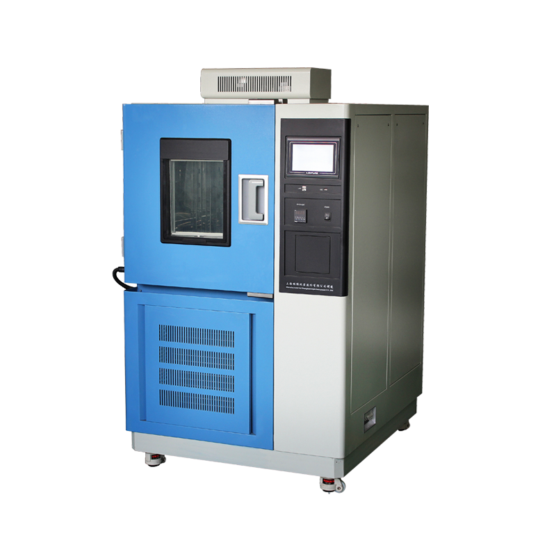

High-low temperature test chambers reproduce a product’s full-life climatic stress within 72 h by cycling between –70 °C and +180 °C at rates up to 5 °C·min⁻¹. During this process, high-pressure refrigerant, high-speed rotating parts, high-current heaters and potentially explosive samples coexist inside the cabinet. Without proper safety design, electric shock, mechanical injury, fire or even explosion can occur. Based on GB/T 10592, IEC 61010-2-012, ISO 13732-1 and 10 000 chamber-years of aftermarket data, this paper systematically reviews the high-risk points in the four stages of “installation–operation–maintenance–emergency” and provides quantifiable control limits and test methods for laboratory managers, EHS engineers and service providers.

2 Installation Stage—Eliminate Risks Before Power-On
2.1 Protective Earthing and Equipotential Bonding
The resistance between the chamber’s protective-earth terminal and the laboratory earth network shall be ≤ 0.1 Ω (GB/T 16895.3). Use yellow-green Cu wire with a cross-section ≥ 4 mm²; series connection to other equipment is forbidden. If the site uses a TN-C system, create a TN-S arrangement by repeated earthing at the distribution panel to prevent enclosure energisation due to PEN conductor breakage.
2.2 Phase Sequence and Phase-Loss Protection
Incorrect phase sequence causes the three-phase fan to rotate in reverse, reducing airflow by 40 %. Heat cannot be removed from heater surfaces, creating local hot spots. Before energisation, check L1-L2-L3 with a phase-sequence indicator; if only single-phase power is available, install an electronic phase-correction module to avoid manual wiring errors.
2.3 Mechanical Fixation and Levelling
Fix the chamber feet to the floor with M12 expansion bolts; the level shall be ≤ 2 mm·m⁻¹ to prevent resonant displacement when the high-speed fan (2 800 r·min⁻¹) runs. Casters must have dual brakes that automatically lock on slopes ≥ 5° to prevent accidental rolling.
2.4 Flammable-Refrigerant Leak Pre-Assessment
When R404A, R23 or other A1 refrigerants are charged > 2.5 kg per unit, the laboratory shall provide forced ventilation ≥ 12 air changes·h⁻¹ and install an infrared refrigerant detector at 2.5 m above floor with a 1 000 ppm alarm set-point that interlocks the main power supply.
3 Operation Stage—Real-Time Monitoring and Access Control
3.1 Pre-Start Daily Checklist
a) Visually confirm the door seal is not cut and the magnetic gap ≤ 2 mm;
b) Measure heater-to-earth insulation > 50 MΩ (500 V megger);
c) Scan compressor and fan bearings with an IR thermometer; surface temperature rise ≤ 60 K;
d) Verify the emergency-stop button is reset and the PLC shows no alarms.
3.2 Rotating-Part Access Control
Fan-blade tip linear velocity can reach 45 m·s⁻¹, equivalent to the impact energy of a 5 kg mass falling from 0.5 m. Never open the door while running; if the sample rack must be adjusted, first switch off the main power, wait ~30 s for the impeller to stop, then wear cut-resistant gloves.
3.3 Energised-Sample Electrical Isolation
When testing batteries, power resistors or other self-powered devices, use an external supply and install 1 000 V DC feed-through terminals (withstanding 2 500 V·AC for 1 min) at the lead entry to prevent condensed water from tracking along wires and shorting the terminal strip.
3.4 Redundant Over-Temperature Protection
Besides the main PID controller, an independent mechanical thermostat set at set-point +5 °C with 16 A contacts is wired in series with the heater circuit; a 2.0 MPa pressure switch monitors refrigerant high-side pressure—either limit exceeded will cut the heater contactor within 2 s.
4 Maintenance Stage—Eliminate Hidden Dangers on Schedule
4.1 Heater Carbon Deposit Removal
After 500 h at 150 °C, carbonised deposits may form on heater tubes, increasing thermal resistance by 15 % and raising surface temperature, accelerating insulation ageing. Every 6 months wipe with 5 % citric acid, rinse with DI water and re-measure insulation > 50 MΩ.
4.2 Door-Seal Recovery
Silicone door seals exposed to 85 °C/85 %RH for 1 000 h can develop 20 % compression set, doubling air leakage. Soak in 60 °C water for 15 min to restore elasticity; if set exceeds 30 % replace the seal to ensure leakage ≤ 0.05 m³·min⁻¹ (EN 13141-5).
4.3 Refrigerant Leak Detection
Use helium mass-spectrometer leak testing with leak rate ≤ 1×10⁻7 Pa·m³·s⁻¹; if soap-bubble method is used, any bubble > 1 per min at brazed or threaded joints is unacceptable—re-braze and re-pressure-hold for 24 h with pressure drop ≤ 0.05 MPa.
5 Emergency Stage—From Accident Threshold to Personnel Evacuation
5.1 Electric-Shock / Leakage
Hit the emergency stop, remove the victim with an insulated pole, switch off the main supply, start CPR and call 120. Within 24 h test the 30 mA·A type RCD operating time and confirm ≤ 30 ms.
5.2 Major Refrigerant Leak
Start forced exhaust, evacuate personnel to the up-wind side, enter wearing positive-pressure breathing apparatus, close the cylinder valve and use an explosion-proof fan to dilute to < 400 ppm (PEL).
5.3 Sample Explosion
When internal pressure spikes, the top bursting disc (2 kPa ±10 %) opens to provide directional relief; if the door seal is blown open, activate a CO₂ extinguisher—never use water to avoid secondary short-circuits.
5.4 Cold / Thermal Burns
For −70 °C contact, rewarm with water below 40 °C for 15 min—do not rub; for 150 °C burns, flush with clean cold water for 15 min, cover with sterile dressing and send to hospital.
6 Conclusion
The safety threshold of a high-low temperature test chamber is often hidden in the complacency of “three years without an alarm”. Statistics show that 80 % of accidents occur in years 4–5 when maintenance is lacking. Only by closing the five-ring chain of “earthing–interlocking–pressure relief–monitoring–training” can extreme temperatures and high-pressure refrigerants be kept under control, ensuring reliable test data and the safety of personnel and property. All LINPIN chambers are shipped with dual hardware protection, automatic phase-sequence recognition and refrigerant-leak monitoring as standard, together with life-long safety-record hosting services. If a level-3 over-temperature occurs, switch off immediately and call our hotline +86-400-885-6188—we guarantee on-site arrival within 4 h and system recovery within 24 h, safeguarding your extreme-environment testing.