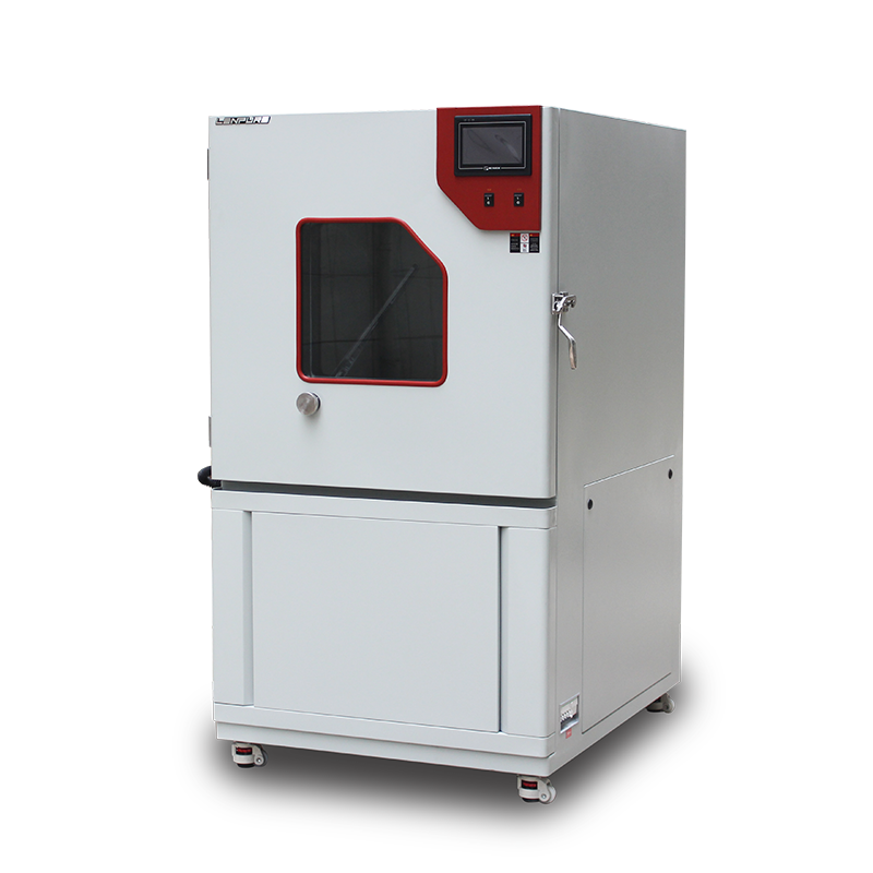
The Dust Test Chamber is the key apparatus for verifying enclosure protection ratings (IP5X, IP6X) and sealing integrity. Its results directly determine whether a product can survive long-term exposure to deserts, mining areas or other dust-laden environments. Field data show that ≈30 % of measurement errors are caused by improper installation, utilities or maintenance rather than by the chamber itself. Drawing on current national/international standards and 20 years of on-site experience of Shanghai LIPIN Instrument Co., Ltd., this document presents a complete, practicable technical code for site selection, installation, commissioning, acceptance and maintenance.
Terms and Normative References
2.1 Terms
Dust Test Chamber – a sealed environmental simulator that circulates calibrated dust in a controlled manner to evaluate the sealing and functional performance of an EUT (equipment under test).
2.2 Normative References
GB/T 2423.37-2006 Environmental testing – Part 2: Test L: Dust and sand
GB/T 4208-2017 Degrees of protection provided by enclosure (IP code)
IEC 60529:2013 Degrees of protection provided by enclosure (IP Code)
GB 50054-2011 Code for design of low-voltage electrical installations
GB 50019-2015 Code for design of heating, ventilation and air conditioning of industrial buildings
Pre-installation Requirements
3.1 Room Independence
The chamber shall be located in a dedicated dust-test room, isolated from salt-fog, vibration, shock or temperature-cycling equipment to prevent cross-contamination. A buffer lobby with interlocked airtight doors and automatic bottom seals is mandatory to avoid dust escape.
3.2 Floor and Load
Typical footprint 1 200 mm × 1 100 mm, weight 600–1 200 kg. Floor: C30 (or higher) concrete, ≥150 mm thick, level within 3 mm per 2 m. For installations above ground floor, a structural calculation (live-load factor ≥1.5) signed by a civil engineer is required.
3.3 Ambient Conditions
Temperature 15 °C–25 °C; relative humidity ≤55 %RH. If the HVAC system cannot maintain these values, install a dedicated air-handling unit to prevent condensation and dust agglomeration.
3.4 Ventilation and Exhaust
A φ150 mm quick-coupling on the chamber roof shall be connected to a galvanized spiral duct terminating outdoors. A weather-proof cowl and a secondary 5 µm dust bag prevent back-flow. Exhaust fan: ≥600 m³/h at 400 Pa, noise ≤65 dB(A).
3.5 Electrical Supply
Power: 3-phase 5-wire AC 380 V ±10 %, 50 Hz, 5.5–9 kW (model dependent).
Earthing: TN-S system, PE conductor ≥6 mm², earth resistance ≤4 Ω.
Distribution board: within 3 m, fitted with 32 A breaker, 30 mA/0.1 s RCD and surge protector Imax ≥40 kA.
Cables: 5 × 4 mm² flame-retardant shielded cable, metal conduit earthed throughout.
Installation Procedure
4.1 Unpacking and Visual Check
Verify items against packing list: main unit, dust-dryer, vibrator, circulation fan, sample turntable, 50 kg medical-grade talcum powder, spares, certificates, software USB. No dents, no cracks in insulation, door gasket continuous.
4.2 Levelling
Using a 0.5-class spirit level, adjust four M16 stainless levelling feet to ≤0.5 mm/m in both axes. Lock counter-nuts and fit 5 mm anti-vibration pads.
4.3 Electrical Wiring
Only licensed electricians shall connect power, control and signal lines in accordance with the wiring diagram supplied.
Heater bank uses Y-Δ starting; wrong phase sequence will reverse the fan and stop dust circulation.
Pt100 sensors are 3-wire; use shielded silver-plated extension leads to prevent EMI drift.
4.4 Duct Connection
Connect exhaust with 150 mm high-temperature fabric flexible section to isolate vibration; outdoor duct slope ≥1 % to prevent rain ingress.
4.5 No-load Commissioning
Power up and verify:
Temperature – set 55 °C, 9-point survey (upper/middle/lower levels) deviation ≤±2 °C.
Humidity – compare sensor with chilled-mirror hygrometer, error ≤±3 %RH.
Dust concentration – laser particle counter, IP6X ≤2 g/m³, fluctuation ≤±10 % in 5 min.
Talcum drying – 80 °C for 2 h, moisture ≤0.5 %.
Acceptance and Hand-over
5.1 Site Acceptance
Joint inspection by user, supplier and accredited third-party body against technical agreement: appearance, structure, functions, accuracy, noise, safety.
5.2 Calibration
Temperature, humidity, dust concentration and air velocity (0.2–2 m/s vertical, adjustable) shall be calibrated by a CNAS-accredited laboratory; recalibration interval 12 months.
5.3 Documentation
Deliverables: Installation & Acceptance Report, Operation & Maintenance Manual, Calibration Certificates, Software Backup, Critical Spare Parts List, Wear-part Drawings.
Operation and Maintenance
6.1 Talcum Powder Management
After every 20 cycles or if caking is observed, remove all powder, sieve through 200 mesh, dry at 80 °C for 4 h and reuse. After five reuse cycles discard and replace to keep silica content low (MIT ≤450 °C explosion risk).
6.2 Filter Cleaning
Primary filter at fan inlet: blow off with clean 0.4 MPa compressed air every 5 tests; replace medium-efficiency filter every 3 months.
6.3 Vibrator Maintenance
Every 6 months check M8 mounting bolts for loosening (paint witness mark); if displacement ≥1 mm re-torque and apply thread-locker. Clean electromagnet pole faces to maintain vibration force.
6.4 Door Seal
Lubricate magnetic gasket with silicone grease every 3 months to avoid cracks. After closing, 5 mm polyurethane foam shall be compressed ≥2 mm; otherwise replace immediately.
6.5 Software Backup
Twice a year archive control software, historical data and user programmes to both cloud and local storage to prevent data loss from IPC failure.
Safety and Emergency
7.1 Dust Explosion Protection
Room equipped with two 5 kg phosphate-free dry-powder extinguishers and two explosion-proof exit lights; naked flames prohibited. Use an explosion-proof industrial vacuum for cleaning.
7.2 Electrical Safety
Follow LOTO (lock-out tag-out) before maintenance; verify zero energy with a multimeter 5 min after power-off.
7.3 Personnel Protection
Operators shall wear KN95 dust masks, safety goggles and anti-static clothing. If talcum contacts skin, rinse with running water for 15 min.
Conclusion
As a high-value precision environmental simulator, the dust test chamber’s installation quality determines its 10-to-15-year accuracy and operating cost. Only by strictly following national standards, manufacturer specifications and the present guide during site selection, installation, commissioning, acceptance and maintenance can the equipment remain in a controlled, stable and traceable metrological state, providing true, accurate and repeatable test data. Shanghai LIPIN Instrument Co., Ltd. operates a 2 000 m² full-machine test centre and a 160 m² precision calibration laboratory, offering life-cycle services including installation supervision, metrology, explosion-proof upgrades and remote O&M. Customers are welcome to visit our factory for technical exchange and equipment selection.


Copyright © 2025 Shanghai Linpin Instrument Co., Ltd Copyright
| ICP Number:Shanghai ICP Record No. 12029585-7
| Sitemap


 EN
EN
 中文
中文 Pусский
 Tiếng Việt
 ภาษาไทย
 پاکستانی زبان