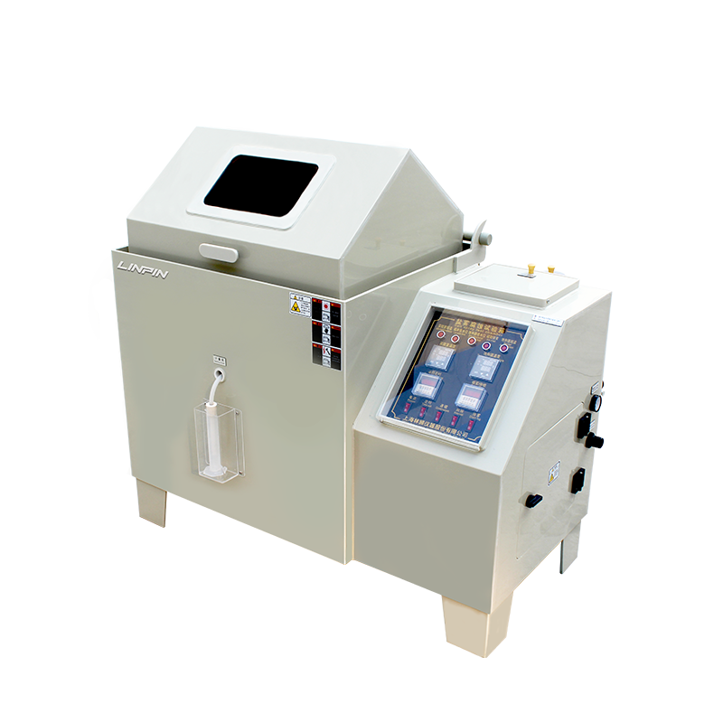
Salt fog (salt spray) chambers are indispensable for evaluating the corrosion resistance of materials and coatings in automotive, aerospace, electronics, hardware, coatings and defense industries. With numerous brands and highly variable quality on the market, buyers need a rigorous, systematic method to identify a chamber that meets technical standards while remaining economically viable and environmentally responsible. Drawing on current industry standards and field experience, this guide presents a six-module decision model that balances performance, reliability, sustainability and ergonomics.
Quantitative Assessment of Volume and Construction Materials
2.1 Volume Determination
The useful volume must satisfy two constraints:
(1) Total test-sample volume ≤ 30 % of the useful chamber volume.
(2) External chamber dimensions < net laboratory space after deducting maintenance aisles.
Generate a 3-D layout that considers sample orientation (hanging, V-tray or rack) to guarantee unobstructed airflow.
2.2 Material Requirements
• Structure: corrosion-resistant rigid PVC with UV stabilizers, wall thickness ≥ 8 mm.
Acceptance test: bend three random samples 90° at 23 °C/50 % RH—no whitening or cracking allowed.
• Heating elements: industrial-grade titanium alloy (TA2 or TA10) with pitting potential ≥ 1.2 V (SCE). Supplier must provide a 1 000 h salt-fog test report showing mass loss ≤ 0.1 mg/cm².
Thermodynamic Efficiency: Saturator (Pressure Vessel) and Energy Use
The saturator pre-heats compressed air to accelerate chamber conditioning. Key points:
• Volume ≥ 10 L to ensure ≥ 30 s air residence time.
• Construction: titanium alloy or PP-lined to resist chloride stress-corrosion cracking.
• PID temperature control at 47 °C ± 2 °C; temperature gradient with test space ≤ 3 °C.
With a properly sized saturator, warm-up energy drops 15–25 % and conditioning time is shortened by ≥ 20 min.
Spray Uniformity and Stability
Spray quality directly affects corrosion deposition rate and test repeatability. Critical subsystems:
4.1 Reservoir Venting
Auto-regulating exhaust valve maintains a slight positive pressure (0.8–1.2 kPa) to prevent stray airflow.
4.2 Atomizer and Nozzle
• Atomizer: PTFE or high-borosilicate glass, surviving 1 000 h continuous 5 % NaCl spray without visible degradation.
• Nozzle: glass, 1.0 mm ± 0.05 mm orifice, spray angle 30°–45°, salt-fallout rate 1–2 mL/80 cm²·h per GB/T 2423.17.
4.3 Solution Return
Removable V-tray channels condensate back to the reservoir, preventing crystalline blockages.
Environmental and Sustainable Design
5.1 Waste-Fog Recovery
Two-stage system:
(1) Primary coil condenses ≥ 80 % of salt fog.
(2) Secondary activated-carbon tower reduces outlet Cl⁻ concentration ≤ 5 mg/m³.
5.2 Solution Recirculation
Reservoir includes filter pads and magnetic rods to remove debris, extending solution change intervals to 720 h.
Safety, Intelligence and Ergonomics
6.1 Safety
• Dual over-temperature protection: electronic controller + independent mechanical thermostat, deviation ≤ ± 2 °C.
• Low-water alarm and auto-shutdown to prevent dry-fire.
• Door electromagnetic lock prevents accidental opening during test.
6.2 Intelligence
• 7-inch color HMI supporting multi-step programs (temperature, spray, dwell, dry).
• On-board data logger stores ≥ 10 000 records, exportable via USB or Ethernet.
• Remote monitoring via RS-485/Modbus for LIMS integration.
6.3 Maintainability
• Pneumatic-assisted lid for single-operator opening.
• Smooth internal radii for easy cleaning.
• Front-mounted sensors and solenoid valves cut maintenance time to < 15 min.
Supplier and Brand Evaluation
7.1 Qualification Checklist
• ISO 9001 and ISO 14001 certifications.
• Compliance with IEC 60068-2-11, GB/T 2423.17, ASTM B117 with third-party test reports.
7.2 Track Record & Performance
Review three-year application data for the same model in the target industry, focusing on:
• Mean Time Between Failures (MTBF) ≥ 5 000 h.
• Spare-part response time ≤ 24 h.
• Customer satisfaction ≥ 90 %.
7.3 After-Sales Service
• 2-year full warranty, optional 5-year extension on core parts.
• On-site training covering operation, calibration, maintenance and troubleshooting.
• Scheduled visits: quarterly in year 1, semi-annually thereafter, with a health-check report.
Technical & Commercial Documentation Closure
Before final approval, require a complete technical proposal including:
(1) General arrangement, piping and electrical schematics.
(2) Material certificates and test reports for critical components.
(3) Energy-consumption and effluent-emission calculations.
(4) Acceptance protocol and warranty clauses.
Conduct technical clarification, on-site due diligence and prototype testing in three successive rounds to minimize operational risk.
Conclusion
Salt-fog chamber selection should transcend the simple price-performance trade-off. By applying the six-module framework—volume/material quantification, thermodynamic efficiency, spray uniformity, environmental design, safety/intelligence and supplier assessment—buyers can pinpoint the optimal solution that maximizes quality, efficiency and sustainability in a complex market landscape.

25.09

Copyright © 2025 Shanghai Linpin Instrument Co., Ltd Copyright
| ICP Number:Shanghai ICP Record No. 12029585-7
| Sitemap


 EN
EN
 中文
中文 Pусский
 Tiếng Việt
 ภาษาไทย
 پاکستانی زبان