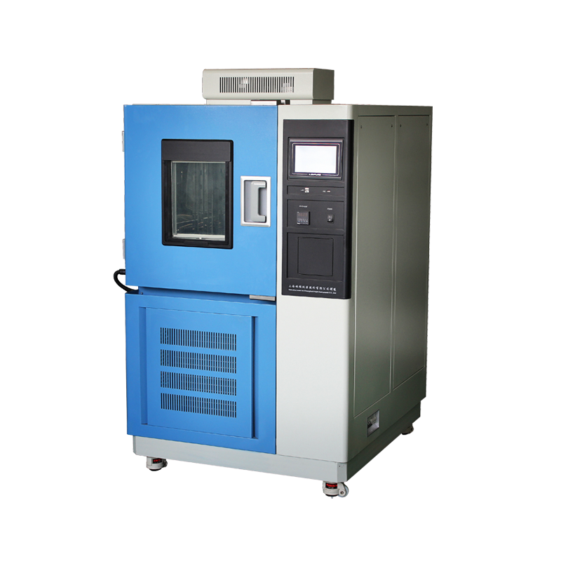

The high-low temperature test chamber is the cornerstone of environmental reliability testing. Its cooling rate dictates test duration and data validity. Field data from 500+ chambers over ten years show that “slow cooling” accounts for 38 % of all malfunctions, second only to “no cooling”. This paper, aligned with GB/T 2423.1 and IEC 60068-3-5, presents a systematic approach to diagnosing and correcting slow-cooling events for laboratories, metrology bodies and manufacturers.

Technical Definition of Cooling Rate
Nominal: empty chamber, +25 °C to –40 °C in ≤ 60 min (JB/T 9512 class A).
Measured: 1 Hz sampling, average of five runs; deviation > +10 % is labelled “slow”.
Boundary conditions: ambient 23 °C ± 2 °C, RH ≤ 65 %, empty, air speed 0.5 m s⁻¹. Any deviation requires correction factor Kθ.
Fault Tree and Weightings
Top-level factors: condenser heat-transfer resistance, ambient coupling, refrigeration circuit, air-side flow, control strategy, load & set-point.
Condenser fouling: 27 % of cases.
Insufficient wall clearance or nearby heat sources: 19 %.
Refrigerant micro-leaks, saturated dryer, expansion-valve drift: 22 %.
Blower speed loss or duct leakage: 15 %.
Conservative PID or faulty defrost logic: 9 %.
Excessive specimen mass or aggressive set-point: 8 %.
Step-by-Step Diagnosis and Quantification
4.1 Condenser Resistance
Measure air-temperature rise ΔT across coil; normal ≤ 8 K, fouled ≥ 12 K.
Measure static-pressure difference ΔP; limit 15 Pa, cleaning required at 30 Pa.
Cleaning: power-off, remove top panel, 0.3 MPa nitrogen blow, 40 °C neutral detergent spray, rinse, 110 °C dry, re-assemble. Expect ≥ 30 % reduction in ΔT.
4.2 Ambient Coupling
Air-cooled units need ≥ 0.6 m from walls, water-cooled ≥ 0.8 m; no ceiling obstruction within 1 m of exhaust.
Ambient range 5–30 °C; every 1 °C above 30 °C lengthens pull-down time by 2.3 %.
Keep ovens or furnaces behind a physical barrier; supply-air temperature must be within 3 K of room air.
4.3 Refrigeration Circuit
R404A at +25 °C ambient: high 1.5 ± 0.1 MPa, low 0.35 ± 0.05 MPa.
High < 1.3 MPa plus low > 0.45 MPa and superheat > 12 K indicate under-charge.
Leak detector sensitivity ≥ 1 g yr⁻¹; annual loss > 1 % requires brazing repair.
Dry-filter temperature difference ≤ 2 K; replace if > 4 K.
Thermal-expansion-valve superheat 6–8 K; electronic valve step-loss < 0.5 %, otherwise replace driver.
4.4 Air-Side Flow
Evaporator face velocity 1.2 ± 0.2 m s⁻¹ (five-point mean).
If < 0.8 m s⁻¹, check blower capacitor, ice or corrosion on impeller, torn flexible duct.
Remedy: change capacitor, rebalance to G 6.3, seal ducts with high-temperature aluminium tape.
4.5 Control Strategy
Defrost initiates when evap. temp. < –25 °C for 40 min; if PID output < 20 % and defrost still triggers, controller misjudges load and reduces speed.
Implement “rate lock-out”: if ΔT/Δt < 0.3 K min⁻¹ for 10 min, defrost is inhibited. PID starting point for empty high-mass chamber: Kp = 1.8, Ki = 0.05, Kd = 0.2; reduce Ki by 30 % when 100 kg aluminium load is present. 4.6 Load & Set-Point Heat load Q = m c ΔT / t. 50 kg steel, c = 0.49 kJ kg⁻¹ K⁻¹, ΔT = 65 K, t = 1 h → Q = 0.44 kW (8.8 % of 5 kW capacity). If Q > 15 %, extend pre-cooling or use step set-points.
Avoid aggressive over-shoot: target –40 °C, do not set –45 °C; instead set –35 °C, wait 10 min, then –40 °C.
Thirty-Minute Field Checklist
Minutes 0–5: verify ambient, wall distance, top exhaust.
Minutes 6–10: read high & low pressure, evap. temp., current.
Minutes 11–20: non-contact ΔT on condenser, velocity grid on evaporator.
Minutes 21–25: inspect filters, capacitor, sight-glass.
Minutes 26–30: log PID output, defrost state, load estimate.
If all values normal yet pull-down > 110 % of nominal, label “hidden system mismatch” and schedule factory calorimeter test.
Maintenance SOP & Intervals
Condenser: daily blow-off, quarterly wash & dry, annual fin-thickness check—replace if < 90 % of original. Dry filter: replace yearly or when ΔP > 0.3 bar.
Blower: visual daily, balance quarterly, grease bearing with 2 g Li-soap grease yearly.
Refrigerant: annual leak test; after recharge run 4 h and analyse acid value < 0.1 mg KOH g⁻¹.
Controller: back-up parameters daily, calibrate sensors quarterly, update firmware and burn-in 72 h yearly.
Closing Remarks
Over ninety per cent of slow-cooling events stem from fouling, ambient issues or minor leaks. Apply the loop “boundary check – quantify – clean/repair – verify” and the chamber usually recovers within two hours. For the remaining ten per cent, factory-level calorimeter testing and model-based re-matching are required. Shift from “fail-and-fix” to “predict-and-prevent” by continuously monitoring discharge pressure, current and condenser ΔT; cloud analytics can issue an alert at a 5 % performance loss, cutting unplanned stops to below one per cent.