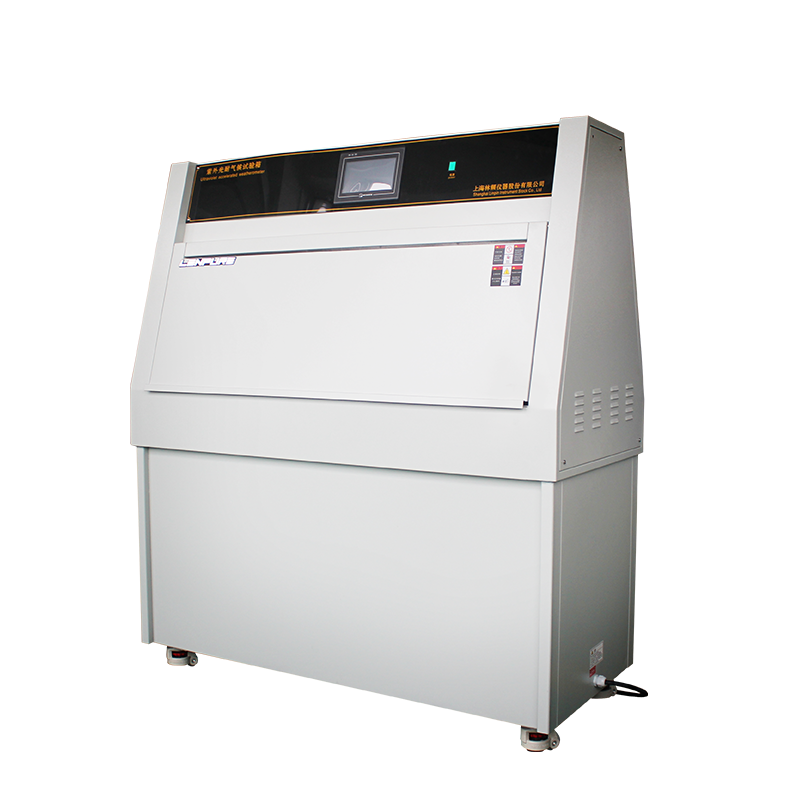
The UV-accelerated weathering test chamber is a key item of equipment used to simulate solar radiation and perform accelerated ageing evaluations on materials. Its electrical system must not only drive high-power UV sources but also acquire and control signals for temperature, humidity, spray, etc. Wiring is the first step of installation and commissioning; any error can cause tripping, component burnout or even electric-shock accidents. Consequently, only qualified electricians who hold a “Special Operation Certificate (Low-Voltage Electrical Work)” and who fully understand the chamber’s electrical schematic and local supply regulations are authorised to carry out wiring. This Guide is prepared with reference to GB/T 5226.1-2019 “Electrical Safety of Machinery”, GB 50054-2011 “Code for Design of Low-Voltage Electrical Installations” and current industrial practice. It systematically describes the wiring sequence, neutral and earthing arrangements, voltage-stability requirements and day-to-day power-supply management for laboratory managers, maintenance personnel and third-party installers.
Pre-installation Preparation
2.1 Unpacking inspection
a) Check name-plate data: rated supply (normally three-phase five-wire AC 380 V ±10 %, 50 Hz), total power (kW), UV lamp power and heater power.
b) Verify documents: electrical schematic, wiring diagram, conformity certificate, residual-current device (RCD) characteristic sheet, warranty card.
c) Confirm no deformation, no loose internal wiring and no damage to insulation.
2.2 Site survey
a) Power capacity: chamber power ≤80 % of the outgoing circuit-breaker rating in the laboratory switch-board; reserve 20 % margin for future expansion.
b) Earthing: building earth resistance ≤4 Ω; for TN-S systems ensure the independent PE bar is reliable.
c) Environment: ambient 5–35 °C, RH ≤85 %, no severe vibration or corrosive gas; floor level within 2/1000.
2.3 Tools & consumables
Insulated gloves and boots, voltage tester, multimeter, 500 V megger, torque wrench, label printer, yellow/green PE wire (≥2.5 mm²), phase sleeves (L1-yellow, L2-green, L3-red), nickel-plated copper lugs (CE), DIN-rail RCD (30 mA, ≤0.1 s).
Wiring Procedure
3.1 Isolation & locking-off
Switch off the upstream feeder; hang “DO NOT SWITCH ON – WORK IN PROGRESS” tag; verify absence of voltage and discharge.
3.2 Main power cable
a) Select 5-core 4 mm² or 6 mm² Cu PVC cable (RVV or YJV); leave 1.2 m service loop.
b) Strip with automatic stripper; sleeve cores with correct phase colours; no nicking of conductors.
3.3 Earthing (PE) system
a) Connect yellow/green PE to the laboratory earth bar first; bar must be welded to the building equipotential bonding network ≥2 × flat-bar width.
b) Chamber PE terminal is M6 Cu stud: use double washer + self-locking nut, torque 3.5 N·m, contact resistance <0.1 Ω. c) Forbidden practices: using water/gas pipes or cable-tray supports as earth; linking PE to neutral; earthing via socket earth pin only. 3.4 Neutral (N) conductor Single-phase loads (lamps, fans, control transformer) plus third-harmonic currents from electronic ballasts can raise N-current to 1.2 × phase current. Therefore N must be equal in cross-section (≥4 mm²) and distributed from a Cu bus-bar; no “borrowed” neutrals for other apparatus. 3.5 Phase conductors (L1/L2/L3) Connect in positive sequence (ABC) to avoid ballast phase-sequence alarms. Bending radius ≥8 × cable OD; use PG21 gland, IP54. 3.6 Control circuits Sensor cables (temp./humidity/irradiance) – shielded twisted pair RVVP 2×1.0 mm², shield earthed at one end only. Keep 24 V control and 380 V power in separate conduits; cross at ≥90° to reduce EMI. 3.7 RCD verification Inject 150 mA fault current with a calibrated tester; trip time ≤40 ms. Monthly, press the built-in “T” button and enter result in the RCD Log Sheet. Voltage Stability & Power Management 4.1 Voltage tolerance GB/T 12325 allows ±7 % on 380 V, but UV lamps are sensitive: 1 % drop in voltage ≈2 % drop in irradiance. Install an AVR (±1 %, ≤50 ms response) if mains variation is large. 4.2 Dedicated circuit Feed the chamber from its own circuit; do not share with air compressors or ovens. Select breaker rating ≥1.25 × rated current, Type D curve to withstand inrush. 4.3 Harmonic control Electronic ballasts can produce THDi ≈25 %. When several chambers share a feeder, calculate neutral harmonic summation; install an active power filter (APF) if THDi >10 %.
4.4 Power-down sequence
Switch off lamps, heater and spray circuits first; wait until internal temperature <60 °C, then isolate mains. If UPS is used for data logging, size it for controller only, not lamps, to avoid deep discharge. Maintenance & Service Safety 5.1 Daily checks Inspect PE lug for oxidation or looseness; cable sheath for cracks; RCD indicator normal. 5.2 Periodic insulation test After 48 h shutdown, 500 V megger: power circuit ≥2 MΩ, control circuit ≥1 MΩ. If reading falls >30 %, sectionalise and locate fault.
5.3 Cleaning
Before cleaning lamps or reflectors, isolate and lock-off supply. Use anhydrous ethanol and non-woven cloth; live cleaning is forbidden.
5.4 Fault intervention
If RCD trips:
Cannot reset: measure N-PE resistance with multimeter, rule out short.
Instant trip on reset: unplug lamp modules one by one to locate faulty ballast.
Never bypass or disable the RCD.
Conclusion
The quality of wiring determines the chamber’s service life, test accuracy and personnel safety. Strict compliance with national electrical codes, the sequence “PE first, N second, phases last”, and the principles of “dedicated circuit, stabilised supply, regular verification” are essential. Every user organisation should establish an “Electrical Safety Operation Procedure”, include it in annual training and apply a “one-strike veto” to violations, thereby ensuring true prevention of accidents.


25.03
25.06

Copyright © 2025 Shanghai Linpin Instrument Co., Ltd Copyright
| ICP Number:Shanghai ICP Record No. 12029585-7
| Sitemap


 EN
EN
 中文
中文 Pусский
 Tiếng Việt
 ภาษาไทย
 پاکستانی زبان