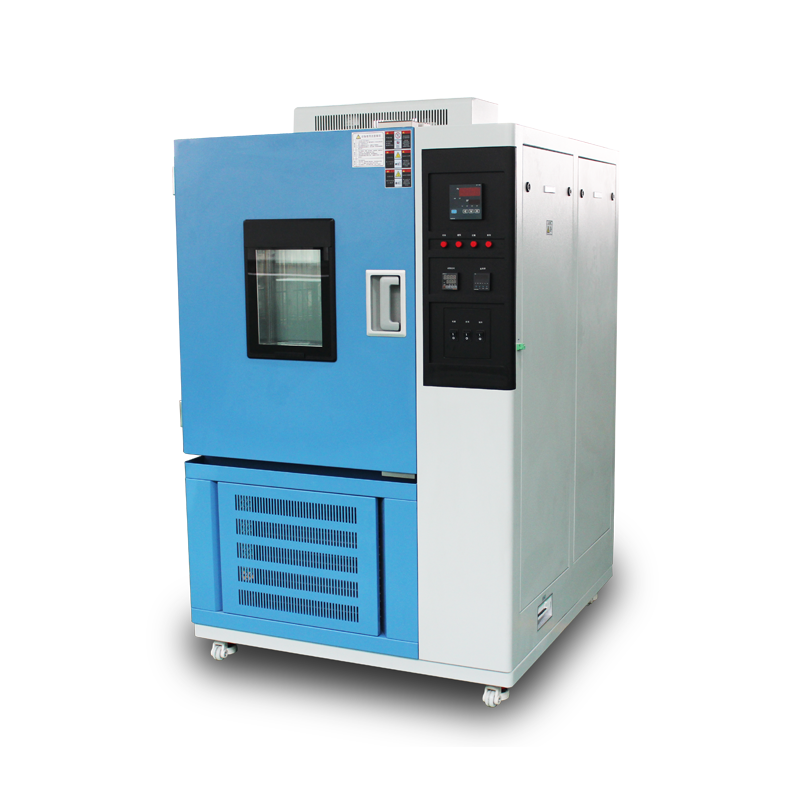

In the aerospace, automotive, home-appliance and materials-science sectors, products must routinely undergo prolonged and repeatable exposure within the −80 °C to 0 °C range to verify functional integrity and service life under extreme cold. Nature cannot supply a continuous, controllable and stable sub-zero environment; consequently, low-temperature test chambers are employed to create an artificial cryogenic duty. This paper systematically explains—through the four lenses of thermodynamic principle, system architecture, energy-transfer path and operational protocol—the internal mechanism by which these chambers establish and maintain a stable low-temperature environment, as well as the external safeguards that guarantee long-term reliability.
Thermodynamic Foundations and Refrigeration Cycle

2.1 Ideal Reverse-Carnot Model
A low-temperature test chamber is essentially a heat engine operated in reverse, whose objective is to “pump” heat from the working space to the ambient. The ideal reverse-Carnot cycle consists of two isothermal and two adiabatic processes; its coefficient of performance (COP) depends solely on the temperatures of the cold and hot reservoirs. In practice, a vapour-compression cycle approximates this ideal.
2.2 Four Core Stages of the Vapour-Compression Cycle
(1) Compression: A hermetic scroll compressor raises the low-pressure, low-temperature refrigerant vapour to a high-pressure, high-temperature superheated state; the electrical work input is converted into an enthalpy rise that drives subsequent heat rejection.
(2) Condensation: The hot, high-pressure vapour enters a micro-channel, parallel-flow condenser where it exchanges sensible and latent heat with room air (or cooling water), condensing into a high-pressure sub-cooled liquid.
(3) Expansion: The high-pressure liquid undergoes adiabatic throttling through an electronic expansion valve or capillary tube; pressure and temperature plummet, yielding a low-temperature two-phase mixture.
(4) Evaporation: The cold two-phase refrigerant flows through the internal evaporator, absorbs heat from the specimen and chamber walls, evaporates into a low-pressure vapour and returns to the compressor, closing the cycle.
System Configuration and Energy Matching
3.1 Cascade Refrigeration Architecture
When the target falls below −40 °C, a single refrigerant becomes impractical owing to excessively low evaporating pressure and high compression ratio. A binary cascade is therefore adopted: the high-temperature stage (R404A) rejects heat at around −35 °C, while the low-temperature stage (R23 or R508B) evaporates near −85 °C. The two stages are thermally coupled via a plate-type cascade condenser, accomplishing stepped heat transfer.
3.2 Variable-Capacity Energy Modulation
A variable-speed compressor paired with a PWM-driven electronic expansion valve matches instantaneous cabinet heat load in real time. A PID algorithm continuously adjusts compressor speed and valve opening, suppressing temperature overshoot while minimising energy consumption.
3.3 Multi-Mode Heat-Transfer Enhancement
(1) Evaporator side: Internally grooved copper tubes fitted with hydrophilic aluminium fins increase the refrigerant-side heat-transfer coefficient; an adjustable-speed centrifugal fan generates forced convection, holding temperature uniformity within ±0.5 °C.
(2) Condenser side: φ7 mm micro-channel flat tubes combined with corrugated air-side fins and a variable-speed axial fan ensure that condensing temperature does not drift significantly with rising ambient temperature.
3.4 Vacuum Insulation and Thermal-Bridge Suppression
Chamber walls employ a 100 mm polyurethane foam + VIP (vacuum-insulation panel) composite with thermal conductivity ≤0.004 W m⁻¹ K⁻¹. Door frames use dual silicone gaskets plus stainless-steel heater lines to eliminate frost formation and thermal bridging, limiting heat leakage to ≤0.3 %·K h⁻¹.
Control Strategy for Stable Low-Temperature Operation
4.1 Cascade Control Architecture
The primary loop regulates chamber air temperature; the secondary loop monitors evaporating pressure, indirectly reflecting evaporator capacity and preventing lubricant return problems at low pressure.
4.2 Feed-Forward Heat-Load Compensation
Event-triggered signals (door opening, fan step-change, defrost initiation) prompt the controller to pre-emptively raise compressor speed, curbing temperature excursions.
4.3 Intelligent Defrost Logic
When frost thickness raises the air-side pressure drop to a preset threshold, the system switches to hot-gas bypass defrost, using high-temperature discharge gas to melt frost. Defrost duration ≤3 min, with chamber temperature rebound ≤1 °C.
Operation & Maintenance Protocols and Safety Management
5.1 Prohibited Hazardous Media
Flammable, explosive or readily polymerising substances—e.g. diethyl ether, ethanol, gasoline, nitroglycerine, methane, acetylene—must never be placed inside the chamber, lest they form explosive hydrates or detonable mixtures at low temperature.
5.2 Scheduled Cleaning and Calibration
(1) Every 50 h inspect evaporator fin frost; remove superficial frost with a soft brush if required.
(2) Every 200 h wipe internal walls with anhydrous ethanol to prevent grease or silicone volatiles from contaminating sensors.
(3) Every six months perform a three-point calibration of temperature sensors against a standard platinum resistance thermometer; measurement error must remain ≤±0.1 °C.
5.3 Lubrication and Wear Management
Low-temperature compressors use POE ester oil with excellent low-temperature fluidity. After every 1 000 running hours, sample and analyse acid number and moisture; replace oil if acid number >0.1 mg KOH g⁻¹.
5.4 Electrical Safety
All electrical components comply with IEC 61010-1 over-voltage Category II and pollution degree 2. Chamber ground resistance ≤0.1 Ω; residual-current device rated ≤30 mA to protect personnel in humid environments.
Conclusion
Through cascade vapour-compression refrigeration, multi-mode heat-transfer enhancement and high-precision closed-loop control, low-temperature test chambers deliver a stable environment within −80 °C to 0 °C, exhibiting fluctuations ≤±0.2 °C and uniformity ≤±0.5 °C. The system is essentially a precision thermal-management platform bounded by the second law of thermodynamics and implemented via engineering control theory. Only by thoroughly understanding the energy-conversion principles of the refrigeration cycle and rigorously enforcing operation, maintenance and safety protocols can long-term reliability be assured, providing a robust cryogenic testing platform for advanced manufacturing sectors such as avionics, new-energy vehicle batteries and semiconductor devices.