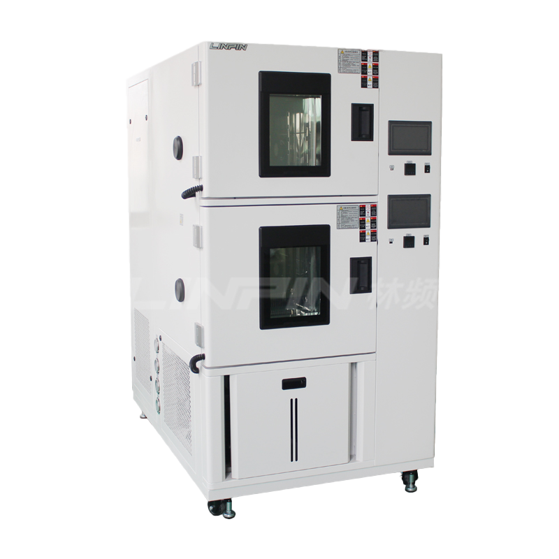
With the continuous tightening of ingress-protection requirements in automotive electronics, low-voltage power distribution and photovoltaic industries, repeatable, quantifiable and traceable artificial-rain testing has replaced the traditional “splash-and-inspect” approach and become the core means of verifying sealing performance. By programmatically replicating complex scenarios such as natural precipitation, road splash and high-pressure car-wash jets, modern rain test chambers can accomplish—within a single laboratory enclosure—IPX1 to IPX6K ratings and even customised cycles that combine driven rain, icing and high-humidity heat.
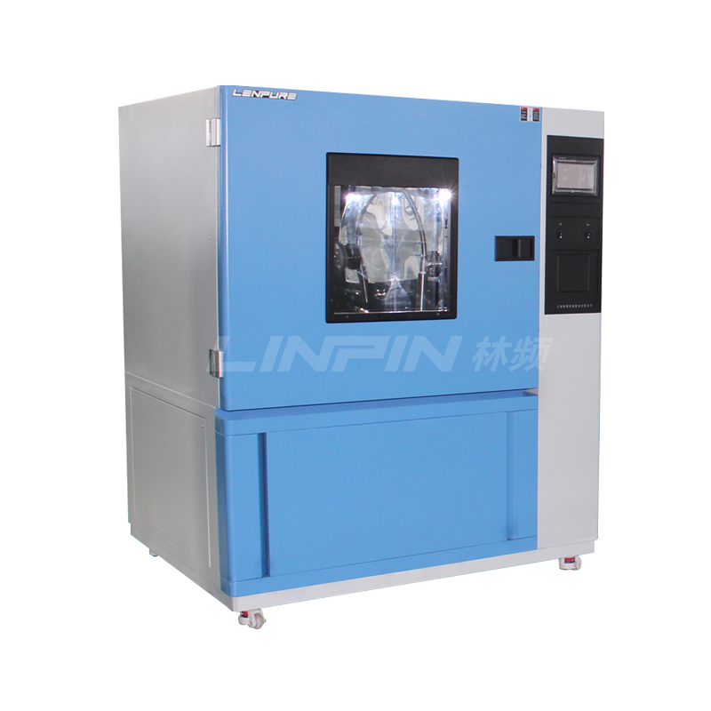
This paper uses the three-stage sequence (drip, high-intensity shower, driven-rain) as its backbone and systematically reviews the technical logic, parameter limits and quality-control essentials, providing a reference for R&D, testing and equipment procurement.
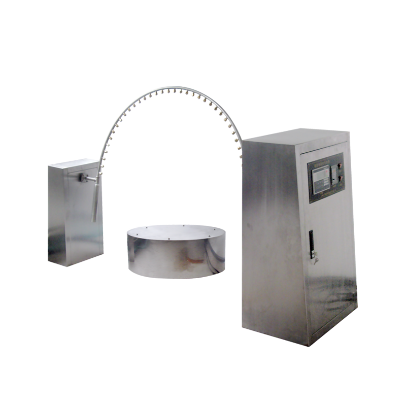
System Architecture of a Rain Test Chamber
Water-supply module: fully-recirculating 316 L stainless-steel tank, multi-stage filtration (50 µm bag + 1 µm cartridge), variable-frequency constant-pressure pump (0–600 kPa, stepless); standard make-up water is de-ionised (< 5 µS cm⁻¹) to prevent nozzle fouling.
Spray matrices
a) Drip zone: SUS 304 laser-perforated plate, Ø 0.4 mm holes on 22–25.4 mm square pitch, 1.8 % open area; rear plenum maintains 10 ± 0.5 kPa static pressure, giving an adjustable drip rate of 1.0–2.0 mm min⁻¹.
b) High-intensity zone: one ISO 12103-1 A2 flat-fan nozzle per 0.56 m², 60° spray angle, 276 ± 10 kPa working pressure, median droplet diameter 2.3 mm (calibrated by laser diffractometer).
c) Driven-rain zone: annular wind-tunnel with axial fan 0.5–10 m s⁻¹, turbulence intensity ≤ 10 %; 3-D ultrasonic anemometer calibrated 1 m ahead of specimen; nozzles at contraction exit, droplet range 0.5–4 mm, horizontal yaw 0–45° adjustable.
Recovery & metering: floor grid → cyclone settler → magnetic-inductive flow meter (± 0.5 % RDG), enabling real-time closed-loop measurement of leakage and spray intensity.
Monitoring & traceability: PLC logs pressure, flow, wind speed and water temperature (18 ± 5 °C); synchronously triggers 4 K colour industrial camera; optional sodium-fluorescein (C.I. Acid Yellow 73) 0.2 g L⁻¹ tracer gives ≤ 0.1 mm leak-point resolution under UV-A illumination.
Three-Stage Test Procedure in Detail
2.1 Drip Test (simulating roof condensation or light rain)
Pre-conditioning: 4 h at 23 °C / 50 % RH to eliminate surface condensation.
Set-up: test surface horizontal, laser-drilled plate 200 ± 20 mm above, acrylic side shields prevent lateral splash.
Parameters: 1.0 mm min⁻¹ for 10 min (IPX1 lower limit); for tougher margin step up to 3.0 mm min⁻¹ in 10-min stages.
Acceptance: < 0.5 cm² visible internal staining and no stream; fluorescent spots photographed and traced to seal compression or weld defects.
2.2 High-Intensity Shower (simulating cloud-burst or car-wash)
Transfer: within 30 s of drip test to avoid surface drying.
Layout: nozzle array on top and four sides, ≥ one spray cone per 4.8 cm²; 15–25 % overlap verified by laser projector to avoid over-erosion.
Pressure/flow: 276 kPa delivers 12.5 L min⁻¹ per nozzle; total flow scales linearly with envelope area; duration 30 min. Optional thermal shock by cycling between 5 °C and 85 °C spray water to test seal thermal expansion synergy.
QC: inlet pressure sampled every 60 s, auto-compensated within ±5 %; 1 000 fps colour camera verifies cone integrity (no voids or bifurcation).
2.3 Driven-Rain Test (simulating high-speed driving or typhoon rain)
Wind field: empty-tunnel calibration at 1, 3, 6, 9 m s⁻¹ using multi-point hot-wire; typical passenger-car bulkhead tested at 9 m s⁻¹, lamps at 6 m s⁻¹.
Droplet control: needle valve + gas–liquid two-phase algorithm, 0.5–4 mm distribution, count median 1.8 mm; 0.2 g L⁻1 fluorescein for visibility without altering surface tension (≤ 0.05 N m⁻¹).
Yaw & duration: 0–45° in 15° steps, 10 min each, total 40 min; specimen rotated 180° around vertical axis for bilateral exposure.
Pass criteria: functional test (500 VDC insulation, ≥ 10 MΩ) within 2 h; no water inside; fluorescent ingress depth < 0.1 mm by confocal microscopy if present. Key Influence Factors & Error Control Water quality: high Ca²⁺/Mg²⁺ changes droplet impact angle; replace de-ionised water every 50 h and maintain pH 6.5–7.2. Nozzle wear: stainless nozzle orifice enlarges ~4 % after 200 h, flow +6 %; monthly optical-projection check, replace if out of tolerance. Wind-droplet coupling: high airflow shatters large drops; Stokes-number analysis ensures ≤ 10° deviation for 4 mm droplets at 9 m s⁻¹. Specimen mounting: fixture natural frequency > 150 Hz to avoid micro-motion under rain excitation that could falsify sealing.
Test Report & Data Traceability
A complete report includes: applicable standards (IEC 60068-2-18:2017, ISO 20653:2020, customer specs); before/after photos; real-time curves (flow, pressure, wind, temperature); fluorescent-leak images with dimensional data; functional-test results; uncertainty budget (flow ±0.5 %, wind ±2 %, droplet size ±5 %). Raw data are encrypted and uploaded to MES, retained ≥ 10 years and QR-code traceable.
Equipment Selection & Maintenance
Internal dimensions: ≥ 30 % larger than specimen envelope to avoid wall splash; traction-battery packs typically require 3 m × 2 m × 2 m.
Materials: full 316 L stainless, weld Ra ≤ 0.8 µm to minimise bio-fouling.
Control system: Ethernet/IP & CAN bus, remote OTA upgrade; FAT/SAT/IQ/OQ/PQ five-step validation templates included.
Maintenance cadence:
Daily – drain sump, UV lamp self-check.
Weekly – nozzle probing, filter ∆P check.
Monthly – external calibration of anemometer & flow meter.
Yearly – full-machine metrology, seal-gasket replacement.
Conclusion
The three-stage sequence “drip – heavy shower – driven rain” compresses months of outdoor exposure into a 90-minute laboratory cycle. Coupled with fluorescent tracing, high-speed imaging and closed-loop data, it makes leakage visible, risk quantifiable and improvement traceable. With the proliferation of high-voltage vehicle systems, ADAS sensors and outdoor energy-storage products, future rain testing will evolve toward higher energy (IPX9K 80 °C, 80 bar), more complex coupling (salt-fog + rain + freeze cycling) and on-line AI judgement. Only by simultaneously deepening capabilities in hardware, algorithms and standards can enterprises stay ahead in the global race for ingress-protection leadership.








Copyright © 2025 Shanghai Linpin Instrument Co., Ltd Copyright
| ICP Number:Shanghai ICP Record No. 12029585-7
| Sitemap






 EN
EN
 中文
中文 Pусский
 Tiếng Việt
 ภาษาไทย
 پاکستانی زبان