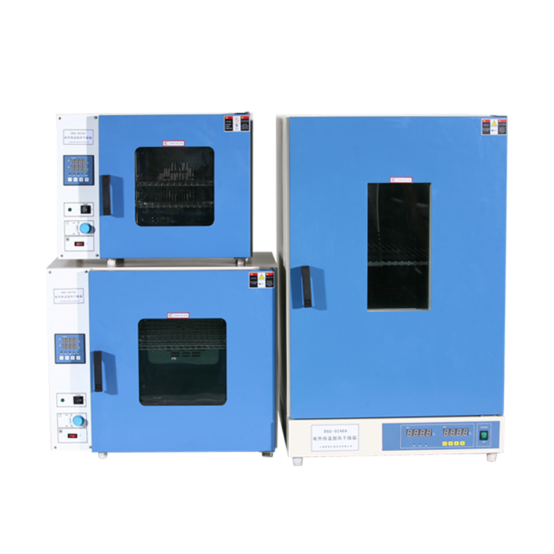
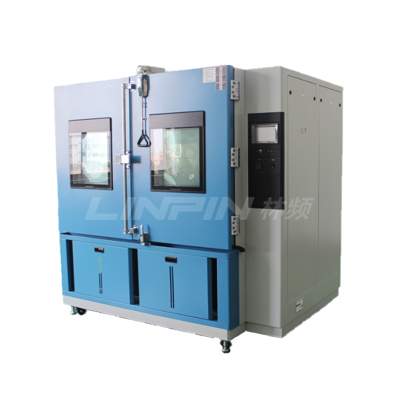
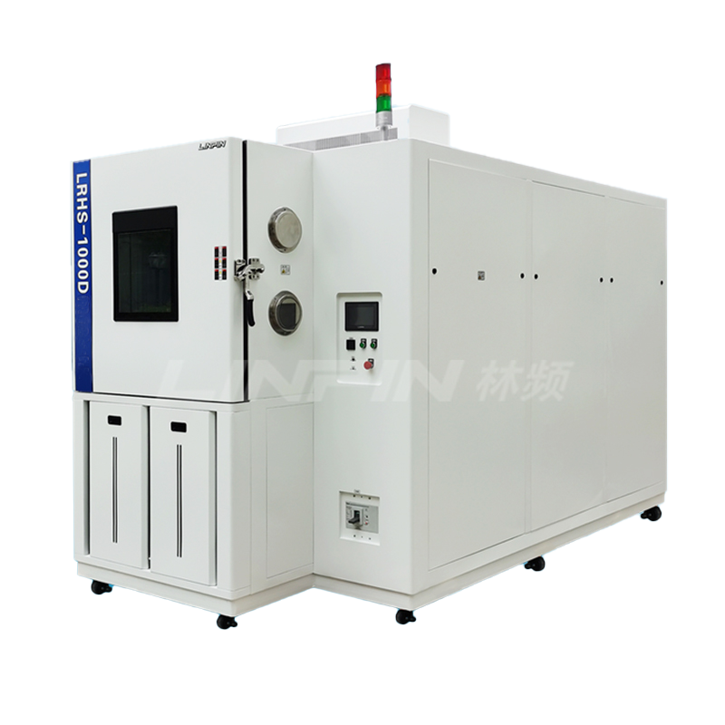
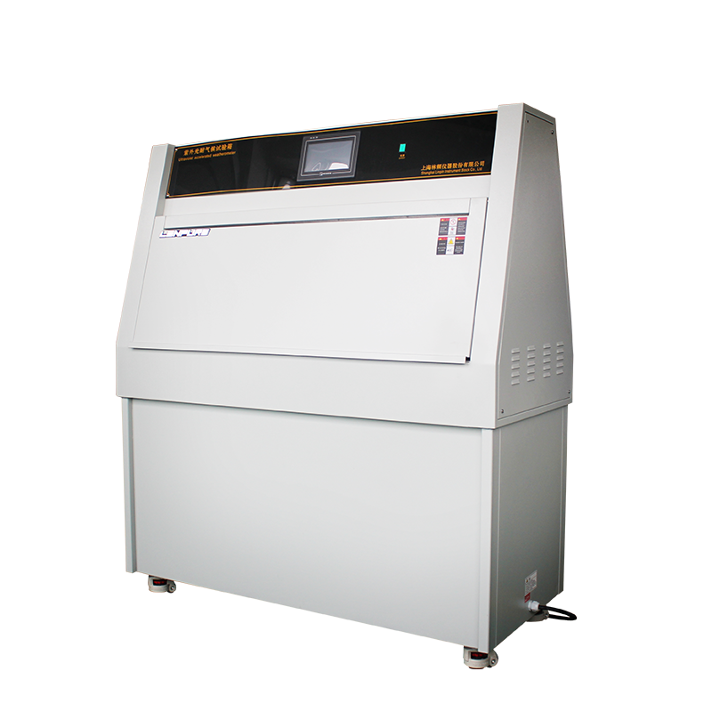
In order to verify the ability of satellite components to withstand vacuum thermal environments, a thermal vacuum chamber is used for testing. The purpose is to validate the rationality of the design and identify defects in the components, materials, and manufacturing processes. Here is how to conduct the test using a thermal vacuum chamber:

Satellite Component Thermal Vacuum Test Method:
Test Equipment:
Thermal vacuum chamber
Test Sample:
Satellite component
Test Procedure:
Start the test equipment and activate the vacuum pumping system to reduce the pressure inside the vacuum chamber from normal ambient pressure to the required test pressure value.
Cool down. Activate the cooling and temperature control system to lower the component temperature from normal ambient temperature at the temperature change rate specified in the dedicated test technical document. When the temperature displayed by the control thermocouple sensor reaches and stabilizes at the required lowest test temperature, maintain this temperature for the specified duration, conduct performance tests on the component, and record the results. Then, end the low-temperature holding state.
Heat up. Activate the heating and temperature control system to raise the component temperature from the low-temperature test temperature at the temperature change rate specified in the dedicated test technical document. When the temperature displayed by the control thermocouple sensor reaches and stabilizes at the required highest test temperature, maintain this temperature for the specified duration, conduct performance tests on the component, and record the results. Then, end the high-temperature holding state.
Cool down again. Lower the component temperature from the high-temperature test temperature at the temperature change rate specified in the dedicated test technical document until it reaches normal ambient temperature, completing one full test temperature cycle.
For components requiring multiple temperature cycles, repeat steps 2 to 4 until the specified number of temperature cycles is reached.
After the component and the entire thermal vacuum simulation chamber have returned to normal temperature, stop the vacuum pumping. If necessary, conduct a performance test on the component.
Before repressurizing the vacuum chamber, during the process of raising the temperature of the heat sink to room temperature at low temperature, the external surface temperature of the component should be at least 10℃ higher than the temperature of the heat sink.
Use the repressurization system of the equipment to inject dry, clean, and non-polluted gas into the space simulation chamber to repressurize it, and then remove the component.







Copyright © 2025 Shanghai Linpin Instrument Co., Ltd Copyright
| ICP Number:Shanghai ICP Record No. 12029585-7
| Sitemap






 EN
EN
 中文
中文 Pусский
 Tiếng Việt
 ภาษาไทย
 پاکستانی زبان