


Climate Chambers for JESD22-A104D: Temperature Cycling
The Principle/Application of Environmental Test Chambers high and low temperature humidity climate chambers.High and low temperature environmental test chambers are a must-have test machine for industries like aerospace, automotive, family appliances, scientific research, etc. It is used to test and determine the parameter and performance of test specimen bearing the high or low temperature, humid and programmable temperature humidity simulations.
Advantage of Shanghai Lenpure Instrument Stock Co., Ltd.
1. With independent intellectual property rights and design patents and master the environmental test box core technology
2. The control instrument is the easy-to-operate UNIQUE (Japan) which can be remotely controlled.
3.The refrigeration system uses Tecumesh (France) compressor and is equipped with condensate water tray.
4. The core electrical components are Schneider and other well-known brands.
5. Advanced design concept: water and electricity layouts are separated.
6. The bottom of the working room (test area) is drainage slot for the purpose of preventing condensation, to maximize the protection of the test specimen.
7. Lights system is Philips kit. The viewing window is of funnel-shaped design with defrosting glass for a wide and clear visual sight.
8.Unique leakage protection with more secure operations.
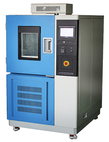
Overview of the environmental test chambers of Lenpure
|
No. |
Description |
| 1 | Observation window |
| 2 | Ethernet interface |
| 3 | Controller |
| 4 | USB interface |
| 5 | Main switch |
| 6 | Emergency button |
Lenpure's high and low temperature humidity climate chambers can meet various kinds of the standard, which includes IESD A 104D: Temperature Cycling.
This specification applies to single-, dual- and triple-chamber temperature cycling and covers component and solder interconnection testing. It should be noted that this specification does not cover or apply to thermal shock chambers.
In single chamber cycling, the load is placed in a stationary chamber and is heated or cooled by introducing hot or cold air into the chamber.
In dual-chamber cycling, the load is placed on a moving platform that shuttles between stationary chambers maintained at fixed temperatures.
In triple-chamber temperature cycling there are three chambers and the load is moved between them.
This test is conducted to determine the ability of components and solder interconnects to withstand mechanical stresses induced by alternating high- and low-temperature extremes.Permanent changes in electrical and/or physical characteristics can result from these mechanical stresses.
Apparatus
The chamber(s) used shall be capable of providing and controlling the specified temperatures and cycle timing in the working zone(s). when the chamber is loaded with a maximum load Direct heat conduction to sample(s) shall be minimized. The capability of each chamber achieving the sample temperature requirements shall be verified across each chamber by one on both of the following methods:
a) Periodic calibration using instrumented parts and a maximum load, and continual monitoring during each test of such fixed tool thermocouple temperature measurement(s) as adequate to ensure run-to-run repeatability.
b) Continual monitoring during each test of an instrumented part or parts placed at worst-case temperature locations (for example, this may be the corners and middle of the load).
Procedure
Sample(s) shall be placed in such a position with respect to the air stream such that there is substantially no obstruction to the flow of air across and around each sample(s).
When special mounting is required, it shall be specified. The sample shall then be subjected to the specified temperature cycling test condition for the specified number of cycles (e.g., JESD47 for qualification or as agreed to between the supplier and user).
Completion of the total number of cycles specified for the test may be interrupted for interim end-point testing, test chamber loading or unloading of device lots, electrical test of samples at specified intervals or as the result of power or equipment failure.
However, if the aggregate number of times of all interruptions exceeds 10% of the total number of cycles specified, the test must be restarted from the beginning.
If the thermocouple is affixed to the sample body, the amount of glue or tape used shall be minimized to insure proper temperature measurements.
The thermocouple, or equivalent temperature measurement apparatus, attachment method used should ensure that the entire mass of the sample(s) is reaching the temperature extremes and the soak requirements.
5.1 Nominal cycle rates
Nominal cycle rates are dependent on the Soak Mode selected.
5.1.1 Component cycle rates
Typical component level temperature cycle rates are in the range of 1 to 3 cycles per hour (cph).Typical failure mechanisms include, but are not limited to, fatigue (such as metal circuit fatigue) and delamination.
For certain failure mechanisms, such as ball bond integrity, faster rates, >3 cph can be used, if the temperature cycling chambers are capable of meeting the T, nominal and soak requirements for the given Test Condition.
5.1.2 Solder interconnect evcle rates
Typical solder interconnect cycle rates are slower, in the range of I to 2 cph, when solder joint fatigue evaluations are performed.
These include flip chip, ball grid array and stacked packages with solder interconnections. Cycle frequency and soak time is more significant for solder interconnections.
5.1.3 Tin whisker cycle rate
Tin whisker cycle rate shall be about 3 cycles per hour as stated in JESD22-A121.
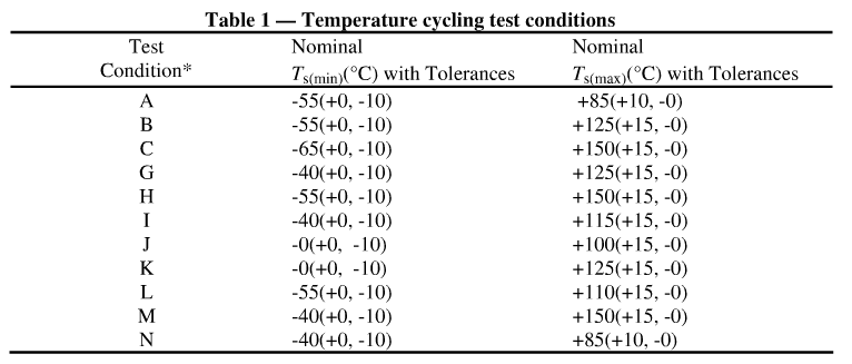
5.2 Maximum and minimum temperature
The maximum and minimum sample temperatures measured shall be within the range stated in Table I for the specific test condition being used and the nominal▲T shall be at least attained.
5.3 Upper and lower soak times
Upper and Lower Soak Times vary by the Soak Mode selected; see Table 2. During this soak time the specimen shall reach the required nominal temperature, either Ts(max) or Ts(min).
5.4Upper and lower soak temperatures
Upper and Lower Soak Temperatures vary with the Test Condition selected; see Table 1.
5.5 Soak modes
Soak Modes are listed in Table 2. Soak Modes with longer soak times than those shown in Table 2 are not compatible with standard cycle rates and should be selected only as required for a specific failure mechanism.
5.5.1 Component soak mode
In component temperature cycling, Soak Mode 1 is typically used.
5.5.2 Interconnect soak mode
Soak Modes 2, 3 and 4 are generally used for solder fatigue and creep testing associated with interconnections such as flip chip or BGA solder joints.
5.5.3 Tin whisker soak mode
Tin whisker soak mode shall be 5 to 10 minutes as stated in JESD22-A121.
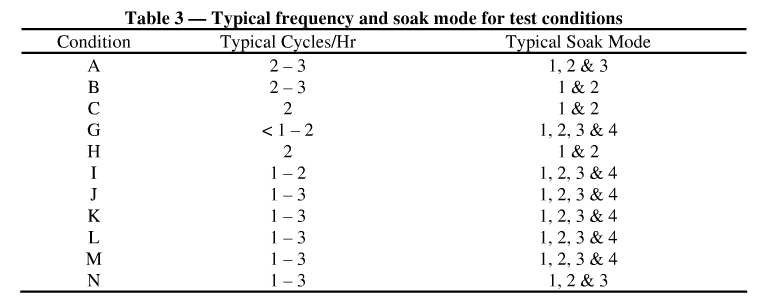
5.6 Nominal cycle time
Nominal cycle times vary with the Soak Mode selected. Table 3 lists typical cycle rates for components versus test condition and soak mode. For solder interconnections, cycle times less than 30 minutes are not recommended.
5.7 Ramp rate
5.7.1 Component ramp rate
Ramp rate is not critical for most component testing with the exception of interconnects, see5.7.2.
5.7.2 Interconnect ramp rate
When testing interconnections for solder joint fatigue, it is important to avoid transient thermal gradients in the samples on test. Samples with large thermal mass and low heat transfer efficiency require ramp rates slow enough to compensate for the thermal mass.
The temperature of the sample should be within a few degrees of the ambient temperature during the temperature ramps. Typical ramp rate for this situation is 15 C/minute or less for any portion of the cycle, with a preferred rate of 10 C to 14 C/minute.
For samples of large thermal mass, use of a single zone chamber may be required to achieve the best ramp rate.
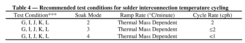
Typical test requirements for solder interconnection are listed in Table 4. The combination of ramp rate and soak time are important when testing solder interconnections.
5.8 Load transfer time (Dual chamber only)
Load transfer time shall be less than I minute. in order to maintain a uniform temperature profile across the load.
5.9 Measurements
Visual examination and electrical measurements. which consists of parametric and functional test. shall be performed as specified in the applicable procurement document or data sheet Electrical test may be performed either in-situ or at an ambient or extreme temperature.
Failure resistance criteria must be adjusted based on the temperature of the sample at time of test. In addition, hermeticity test(s) per JESD22-A109 shall also be performed for hermetic devices.
If you are still interested in any kind of environmental test chambers, and I'm pleased provide some of our details and project to you. That's more, at present we have more attractive price for you. Welcome for inquiry any time, I will reply asap!
If you want to know more information about our products or our company, please feel free to contact sales@lenpure.com or visit http://www.lenpure.com/ .


