


This part of the EN 13523 series specifies the procedures for determining the resistance to salt spray (fog) of an organic coating on a metallic substrate (coil coating). For steel, neutral salt spray (fog) is usually used, and for aluminium, acetic acid salt spray (fog). This standard needs a climatic chamber--salt spray chamber.
A test specimen is exposed to a salt spray (fog) for a specified period of time and assessed for possible corrosion expressed by a degree of a delamination or corrosion and a degree of blistering.
Ordinary laboratory apparatus and glassware, together with the following:
Salt spray cabinet, in accordance with EN ISO 9227.
For neutral salt spray fog, the test solution shall be prepared by dissolving sodium chloride in water of at least grade 3 purity, as defined in EN ISO 3696, to produce a concentration of (50±5)g/l. The sodium chloride shall be white, of minimum assay 99.6% (by mass), and substantially free from copper and nickel; it shall contain no more than 0.1% (by mass) of sodium iodide.
If the PH of the solution is outside the range 6.0 to 7.0, the presence of undesirable impurities in the salt or the water or both shall be investigated. The PH of the test solution shall be adjusted so that the PH of sprayed solution collected within the salt spray cabinet is between 6.5 and 7.2. Any necessary adjustment to the PH shall be made by additions of solutions of either hydrochloric acid or sodium bicarbonate of analytical grade.
For acetic acid salt spray (fog), add a sufficient amount of glacial acetic acid to the sodium chloride solution to ensure that the PH of sprayed solution collected within the salt spray cabinet is between 3.1 and 3.3. If the PH of the solution initially prepared is 3.0 and 3.1, the PH of the sprayed solution is likely to be within the specified limits. Under normal conditions, the level of glacial acetic acid required is approximately 0.3% (by mass).
Cutting tool, with a hard metal tip having a radius or width capable of exposing at least 0.2mm of metal substrate according to EN ISO 17872.
Transparent pressure-sensitive adhesive tape, 25mm wide, with an adhesion strength of (10±1)N per 25mm width when tested in accordance with EN 60454-2.
Sharp drill bit or hole punch, of diameter approximately 5mm for creating the hole.
Appropriate pressing (bending) apparatus, in accordance with EN 13523-19:2011, 5.2 or EN 13523-7:2014, 5.1.2.
Sampling in accordance with EN 13523-0.
Test panels in accordance with EN 13523-0.
Design of the panels:
There are two options, both having the following in common:
--the protection of edges is optional. At least one edge should be unprotected to check the corrosion protection of metal exposed areas;
--if not otherwise specified, the edges of the exposed panels shall be sheared with the burrs away from the test surface;
--the reverse side shall be protected to stop any corrosive influence from the reverse side to the front side. The protection to the reverse side shall be applied before the drilling of the hole;
--the scribes shall be prepared by means of the cutting tool and extend down just through the coating to the substrate. The scribed indentation shall expose at least 0.2mm of metal substrate. If the substrate is zinc- or zinc-alloy coated steel, the scribe shall be to the zinc coating, and not down to the steel;
Special care shall be taken when preparing the scribe. Geometry and depth of the scribe can influence the testing results significantly;
--optionally, make a hole, of diameter approximately 5mm, at 25mm from the bottom edge, at the centre, using the sharp drill bit or hole punch. Start the hole on the test coating so that the burr occurs on the opposite side to the coating under test.
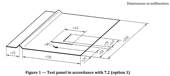
The test panel shall have a size of about 200mm×150mm and shall be flat. The 200mm side shall be in the rolling direction of the substrate.
Make two scribes at 90° to each other. The scribes shall be about 40mm in length with the vertical scribe central to the horizontal but separated by 10mm. The horizontal scribe shall extend to 50mm from the bottom edge, the vertical scribe at 60mm from it.
Make a 90° variable radius bend 25mm from and parallel to the left 200mm edge. The variable radius is bent from 1T to at least 3T as defined in EN 13523-7:2014, 8.2.2.
If the test specimen is exposed the bend is at the left side and the tightest radius at the bottom of the specimen.
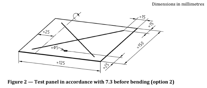
The test panel shall be of suitable size of at least 125mm×150mm and shall be flat. The 150mm side shall be in the rolling direction of the substrate. Two diagonal scribes are carried out crossing each other in the middle of the specimen and extending to within 15mm from the edges in order to reach over the bend.
Make a variable radius bend 25mm from the left or right longest edge, in accordance with EN 13523-7:2014, 8.3. The variable radius is bent from 1T to ≥3T but other bend radii may be agreed between the interested parties depending on the end use of the product. The tightest radius is at the bottom of the panels.
Condition the test panels for at least 24h under laboratory ambient conditions of temperature and humidity. Maintain the cabinet temperature at (35±2)℃.
Pre-heat the compressed air to the required temperature and saturate it before being expanded in the atomiser.
Control the amount of condensate generated during operation in accordance with EN ISO 9227:2017, 4.5, so that 80cm² horizontal surface collect between 1.0ml and 2.0ml of condensate per hour.
Expose the test panels at an angle of between 15° and 25° to the vertical. The panels shall not influence each other.
It is recommended to change the position of the individual panels weekly to facilitate a more uniform exposure in the cabinet.
Include a reference specimen at the same time for exposure to ensure consistent corrosivity of the cabinet.
Place the test panels in the cabinet and expose for the specified or agreed period of time.
Unless otherwise specified or agreed, expose coated steel panels to neutral salt spray (fog) and coated aluminium panels to acetic acid salt spray (fog).
For more details, please feel free to contact sales@lenpure.com
Please visit www.lenpure.com


