


Climate Chambers for IEC 60068-3-5 Environmental Testing Prat3-5: Supporting documentation and guidance Confirmation of the performance of temperature chambers
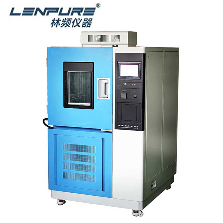
The Principle and Application of Climate Chambers of Temperature Test ChamberHigh and low temperature test chamber is a must-have test machine for industries like aerospace, automotive, family appliances, scientific research, etc. It is used to test and determine the parameter and performance of test specimen bearing the high or low temperature, humid and programmable temperature humidity simulations.
Many different types of environmental test chambers are available foe you. Firstly, your application is primarily going to determine the type of chamber that you need. The better you relay that information to your supplier, and the better your chamber will match your needs.
For example: How big must the chamber be? What is being tested? What is the test standard for the corresponding product? Is it going to be air cooled or water cooled? What temperature range is needed? These are just a few of the necessary questions that must be answered before purchasing climate chambers. But, the most important of these item is the test standard, which is the basic condition for your choice of environmental test chamber.
Shanghai Linpin's high and low temperature environmental test chambers can meet various kinds of test standards, including ICE60068-3-3.
This part of IEC 60068 provides a uniform and reproducible method of confirming that temperature test chambers, without specimens, conform to the requirements specified in climatic test procedures of IEC 60068-2 (all parts) and other standards. This document is intended for users when conducting regular chamber performance monitoring.
Working space part of the chamber in which the specified conditions can be maintained within the specified tolerances.
Temperature rate of change rate, in kelvin per minute, for the transition between two specified temperatures measured at.the centre of the working space.
Measuring chamber performances
4.1Test area environment
The environment around a temperature test chamber may influence the conditions inside the test chamber.The confirmation of performance of temperature chambers should be carried out under standard atmospheric conditions specified in IEC 60068-1.
4.2 Temperature measurement system.
The uncertainty of measurement of the output of the measurement system should be determined by calibration of the system, traceable to international standards (see ISO 10012).
The temperature sensors may be either calibrated platinum resistors or a thermocouple. The thermal response time of the sensors shall be within a minimum of 10 s and a maximum of 40 s for 50% of response. It is preferred that the thermal response time of the entire measurement system to be less than 40 s. The use of sensors that are compliant to IFC 60584-1 tolerance class 1 (for thermocouples) or IEC 60751 tolerance class A (for resistors) is recommended.
4.3 Temperature chamber test specimens
All measurements described in 4.5 are performed with an empty working space. For measuring with test specimens (with or without heat dissipation), see IEC 60068-3-7.
4.4Specified location of temperature sensors in working space
Temperature measuring sensors are located in each corner and in the centre of the working space (see Figure 3, minimum 9 sensors). For temperature chambers over 2 000 1, additional sensors should be located in front of the centre of each wall (see Figure 4. minimum 15 sensors).
The measuring system is to be arranged in such a way that the temperature distribution of the empty test chamber will not be affected. For a large capacity chamber, there may be a significant difference between the temperature control sensor(s) and the temperature at the centre of the working space. It may be necessary to adjust the temperature setting to achieve the necessary tolerance.
For confirmation monitoring, data should be recorded at least once a minute. The device used for recording data from the chamber monitoring sensors should be independent of the chamber control system.
4.5Measurement method
4.5.1General
The temperature output of the temperature measuring system (see Figure 3 or Figure 4) determines, after chamber stabilization, the achieved temperature, temperature fluctuation and temperature gradient of the working space.
For tolerance, the specification of the temperature/humidity chamber or, as necessary, tolerance specified in IEC 60068-2 (all parts).is required to maintain at the centre of the working space. Location of sensor is minimum 9 points or 15 points. This depends on the test chamber size. The measurement method is explained based on 9 points.
Uncertainty of measurement of the temperature measuring system shall be according to IEC 60068-3-11.
4.5.2Achieved temperature
Temperature is achieved when the centre of the working space maintains the tolerance as required by IEC 60068-2 (all parts). An example is shown in Figure 5.
4.5.3Temperature stabilization
Temperature reached and maintained within the allowable range in the working space is shown in Figure 6. Allowable range is based on the temperature fluctuation, temperature variation in space, and temperature gradient as the temperature chamber specification.Specified time T, is minimum 30 min after the measurement points (e.g. N, to Ng) are within the allowable range.
4.5.4Temperature fluctuation
The fluctuation during a specified interval of time at specified temperature points in the working space, after temperature stabilization, is shown in Figure 7.
4.5.5Temperature gradient
As shown in Figure 8, the maximum difference in mean temperature in all measurement points of the effective space shall be the temperature gradient.
4.5.6Temperature variation in space
As shown in Figure 9, temperature variation in space is the difference of the mean temperature at the centre of the working space and the mean temperature of another measurement point. The maximum difference between the centre of the working space and each measuring point shall be stated.
4.5.7Temperature rate of change
As shown in Figure 10, temperature rate of change between specified temperatures shall be calculated with the following method, and indicated in K/min.
Temperature heat-up rate =△t/T1
Temperature cool-down rate = △t/T2
To measure temperature rate of change:
adjust chamber to lowest specified temperature and allow to stabilize;
adjust chamber to highest specified temperature, monitoring the time between the 10 % and the 90 % points of the temperature range;
allow chamber to stabilize at the highest specified temperature;
adjust chamber to lowest specified temperature, monitoring the time between the 90 % and 10 % points of temperature range.
4.6 Standard temperature sequence
The following test sequence is considered to be the minimum recommended to obtain the necessary data for confirmation of the performance of a temperature chamber.
The test sequence is as follows:
start at ambient conditions;
adjust chamber to highest specified temperature and allow chamber to stabilize;
measure performance at highest temperature;
adjust chamber to lowest specified temperature, monitoring rate of change and allow chamber to stabilize;
measure performance at lowest temperature adjust chamber to highest specified temperature, monitoring rate of change;
adjust chamber to atmospheric conditions and allow chamber to stabilize measure performance at atmospheric conditions.
If you are still interested in any kind of environmental test chambers, and I'm pleased provide some of our details and project to you. That's more, at present we have more attractive price for you. Welcome for inquiry any time, I will reply asap!
If you want to know more information about climate chambers or our company, please feel free to contact sales@lenpure.com or visit http://www.lenpure.com/ .


