


Climatic chambers for test standard IEC 61215
This international standard lays down IEC requirements for the design qualification and type approval of terrestrial photovoltaic modules suitable for long-term operation in general open-air climates, as defined in IEC 60721-2-1. It applies only to crystalline silicon modules types. A standard for thin-film modules has been published as IEC 61646. This standard needs many climatic chambers.This standard does not apply to modules used with concentrated sunlight. This object of this test sequence is to be determined the electrical and thermal characteristics of the module and to show, as far as is possible within reasonable constraints of cost and time, that the module is capable of withstanding prolonged exposure in climates described in the scope. The actual lifetime expectancy of modules so qualified will depend on their design, their environment and the conditions under which they are operated.
Eight modules for qualification testing (plus spares as desired) shall be taken at random from a production batch or batches, in accordance with the procedure given in IEC 60410. The modules shall have been manufactured from specified materials and components in accordance with the relevant drawings and process sheets and have been subjected to the manufacturer’s normal inspection, quality control and production acceptance procedures. The modules shall be complete in every detail and shall be accompanied by the manufacturer’s handling, mounting and connection instructions, including the maximum permissible system voltage.
If the bypass diodes are not accessible in the standard modules, a special sample can be prepared for the bypass diode thermal test. The bypass diode should be mounted physically as it would be in a standard module, with a thermal sensor placed on the diode. This sample does not have to go through the other tests in the sequence.
When the modules to be tested are prototypes of a new design and not from production, this fact shall be noted in the test report.
10.10 UV preconditioning test
Purpose
To precondition the module with ultra-violet (UV) radiation before the thermal cycle/humidity freeze tests to identify those materials and adhesive bonds that are susceptible to UV degradation.
a. Equipment to control the temperature of the module while it is irradiated by UV light. The equipment must be capable of maintaining the module temperature at 60℃±5℃.
b. Means of measuring and recording the temperature of the modules to an accuracy of ±2℃. The temperature sensors shall be attached to the front or back surface of the module near the middle. If more than one module is tested simultaneously, it will suffice to monitor the temperature of one representative sample.
c. Instrumentation capable of measuring the irradiation of the UV light produced by the UV light source at the test plane of the modules, within the wavelength ranges of 280nm to 320nm and 320nm to 385nm with an uncertainly of ±15%.
d. A UV light source capable of producing UV irradiation with an irradiance uniformity of ±15% over the test plane of the modules with no appreciable irradiance at wavelengths below 280nm and capable of providing the necessary irradiation in the different spectral regions of interest as defined in 10.10.3.
10.10.3 Procedure
a. Using the calibrated radiometer measure the irradiance at the proposed module test plane and assure that at wavelengths between 280nm and 385nm it does not exceed 250W·m-2 (i.e. about five times the natural sunlight level) and that it has a uniformity of ±15% over the test plane.
b. Mount an open-circuited module in the test plane at the location selected in a), normal to the UV irradiance beam. Make sure that the module temperature is 60℃±5℃.
c. Subject the modules to a total UV irradiation of 15kWh·m-2 in the wavelength range between 280nm and 385nm, with at least 5kWh·m-2 in the wavelength band between 280nm and 320nm, while maintaining the module temperature within the prescribed range.
10.10.4 Final measurements
Repeat the tests of 10.1, 10.2 and 10.3.
10.10.5 Requirements
The requirements are as follows:
- no evidence of major visual defects, as defined in Clause 7;
- the degradation of maximum output power shall not exceed 5% of the value measured before the test;
- insulation resistance shall meet the same requirements as for the initial measurements.
10.11 Thermal cycling test
10.11.1 Purpose
To determine the ability of the module to withstand thermal mismatch, fatigue and other stresses caused by repeated changes of temperature.
10.11.2 Apparatus
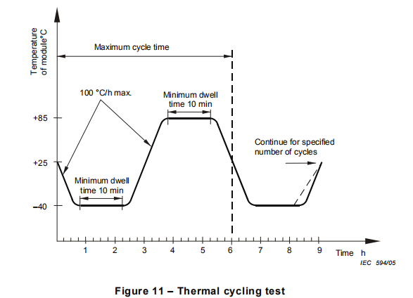
a. A climatic chamber with automatic temperature control, means for circulating the air inside and means to minimize condensation on the module during the test, capable of subjecting one or more modules to the thermal cycle in Figure 11.
b. Means for mounting or supporting the modules in the chamber, so as to allow free circulation of the surrounding air. The thermal conduction of the mount or support shall be low, so that, for practical purposes, the modules are thermally isolated.
c. Means for measuring and recording the temperature of the modules to an accuracy of ±1℃. The temperature sensors shall be attached to the front or back surface of the module near the middle. If more than one modules is tested simultaneously, it will suffice to monitor the temperature of one representative sample.
d. Means for applying a current equal to the STC peak power current of the modules under test.
e. Means for monitoring the flow of current through each module during the test.
A. Install the modules at room temperature in the chamber.
B. Connect the temperature monitoring equipment to the temperature sensors. Connect each module to the appropriate current supply by connecting the positive terminal of the module to the positive terminal of the power supply and the second terminal accordingly. During the 200 thermal cycle test set the current flow to the measured STC peak power current within ±2%. Current flow shall only be maintained when the module temperature is above 25℃. During the 50 thermal cycle test no current flow is required.
C. Close the chamber and subject the modules to cycling between module temperatures of -40℃±2℃ and +85℃±2℃, in accordance with the profile in Figure 11. The rate of change of temperature between the low and high extremes shall not exceed 100℃/h and the module temperature shall remain stable at each extreme for a period of at least 10min. The cycle time shall not exceed 6h unless the module has such a high heat capacity that a longer cycle is required. The number of cycles shall be as shown in the relevant blocks in Figure 1.
D. Throughout the test, record the module temperature and monitor the current flow through the modules.
For more details, please feel free to contact sales@lenpure.com
Please visit www.lenpure.com


